Electronic imaging apparatus
a technology of electronic imaging apparatus and zoom lens, which is applied in the direction of optics, instruments, optics, etc., can solve the problems of inability to achieve size reduction, inability to ensure sufficient optical performance, and difficulty in achieving size reduction in the event that the zoom lens is used with a small-format imaging device, so as to reduce coma, increase zoom ratio, and maintain good field curvature and coma
- Summary
- Abstract
- Description
- Claims
- Application Information
AI Technical Summary
Benefits of technology
Problems solved by technology
Method used
Image

Examples
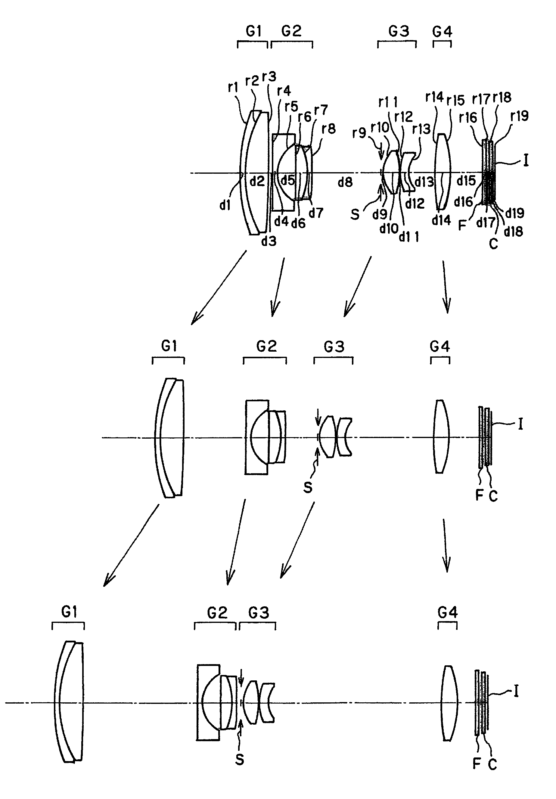
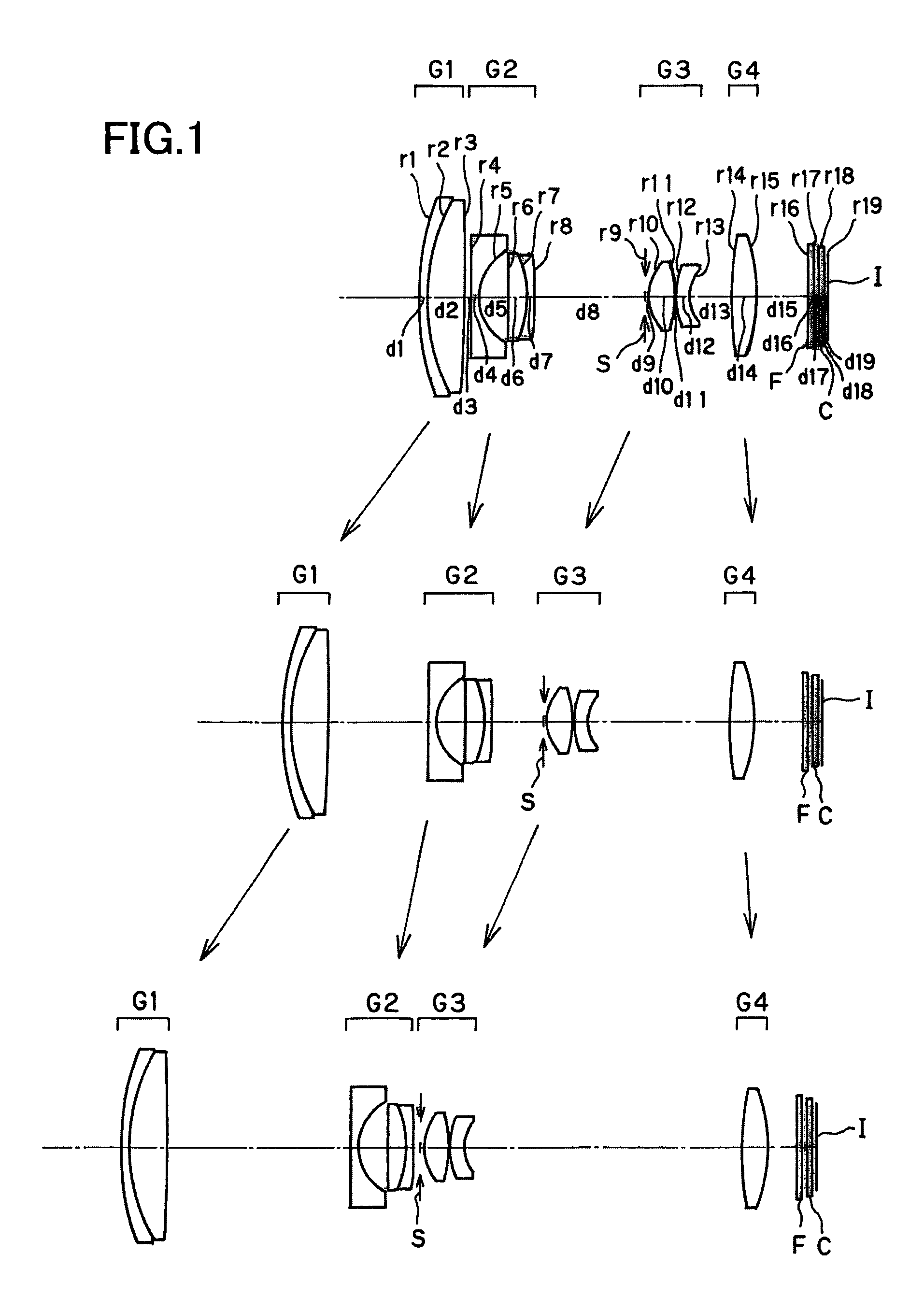
numerical example 1
[0148]
Unit mmSurface dataSurface No.rdndνd 126.6660.801.9228618.90 219.2503.501.7432049.34 3 (Aspheric surface)−176.734Variable 4 (Aspheric surface)−40.9590.801.8061040.92 5 (Aspheric surface)5.5282.69 6−1141.8381.711.9459517.98 7−10.8620.701.8061040.92 8 (Aspheric surface)134.158Variable 9 (Stop)∞0.3010 (Aspheric surface)4.2982.401.4970081.5411 (Aspheric surface)−11.6970.10128.0621.302.0017020.6413 (Aspheric surface)4.214Variable1440.8032.201.7432049.3415 (Aspheric surface)−16.732Variable16∞0.401.5477162.8417∞0.5018∞0.501.5163364.1419∞0.37Image plane∞Aspheric surface data3rd surfaceK = 0.000, A4 = 7.63091E−06, A6 = −4.82260E−094th surfaceK = 0.000, A4 = 1.32148E−03, A6 = −5.72963E−05, A8 = 1.18744E−06,A10 = −1.03698E−085th surfaceK = 0.000, A4 = 1.61134E−03, A6 = 2.28101E−05, A8 = −1.71055E−06,A10 = −1.22624E−098th surfaceK = 0.000, A4 = −4.56444E−04, A6 = −9.41345E−06,A8 = −1.00141E−07, A10 = −2.44141E−1010th surfaceK = 0.000, A4 = −1.33244E−03, A6 = −5.69354E−05,A8 = −2.91994E−06...
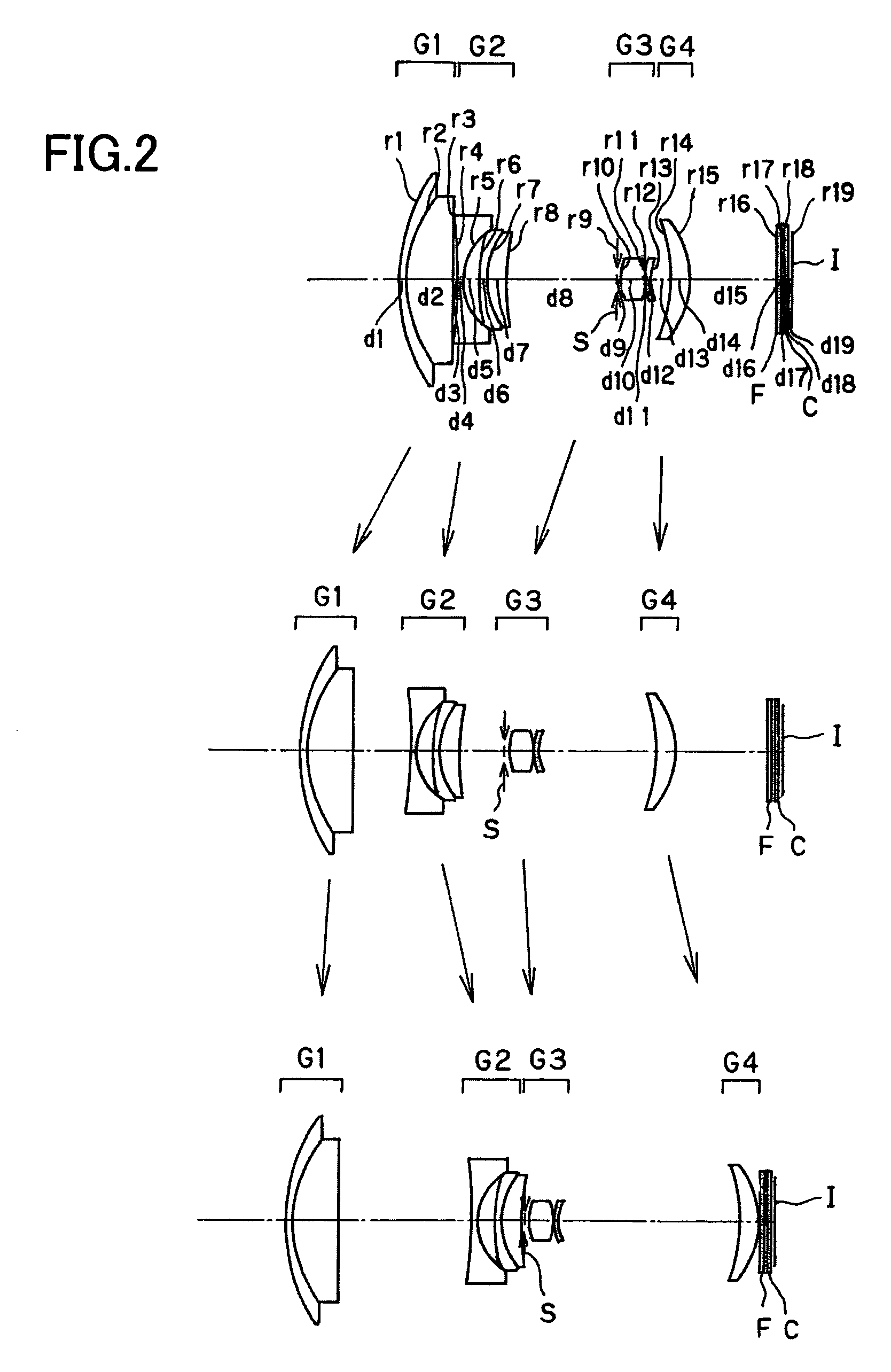
numerical example 2
[0149]
Unit mmSurface dataSurface No.rdndνd 116.4680.601.9459517.98 211.6694.001.7725049.60 3 (Aspheric surface)−298.514Variable 4 (Aspheric surface)−35.6940.501.8348142.71 5 (Aspheric surface)5.2501.50 6 (Aspheric surface)41.1850.501.7725049.60 76.7001.601.9459517.98 821.527Variable 9 (Stop)∞0.3010 (Aspheric surface)4.0992.051.4970081.5411 (Aspheric surface)−10.6340.10124.9960.402.0017020.64133.471Variable14 (Aspheric surface)−10.0821.601.7432049.3415 (Aspheric surface)−5.932Variable16∞0.301.5477162.8417∞0.3018∞0.301.5163364.1419∞0.37Image plane∞Aspheric surface data3rd surfaceK = 0.000, A4 = 2.79166E−05, A6 = −9.61223E−084th surfaceK = 0.000, A4 = 6.02597E−04, A6 = −3.67937E−05, A8 = 9.10591E−07,A10 = −7.79624E−095th surfaceK = 0.000, A4 = 6.24667E−04, A6 = 6.02647E−05, A8 = −2.20783E−06,A10 = −1.71665E−086th surfaceK = 0.000, A4 = 9.33860E−04, A6 = 3.93633E−0510th surfaceK = 0.000, A4 = −2.44420E−03, A6 = −1.76979E−05,A8 = −3.79600E−06, A10 = −7.36605E−0811th surfaceK = 0.000, A4 ...
numerical example 3
[0150]
Unit mmSurface dataSurface No.rdndνd 120.9090.802.0017020.64 216.7203.621.6188163.85 3 (Aspheric surface)−99.283Variable 4 (Aspheric surface)−76.5280.801.8348142.71 5 (Aspheric surface)7.1332.58 6−206.9231.632.1022516.79 7−18.6400.801.8348142.71 8 (Aspheric surface)54.142Variable 9 (Stop)∞0.3010 (Aspheric surface)5.5932.491.6935053.2111 (Aspheric surface)−19.4730.08125.5721.461.4970081.541337.0890.712.0033028.27143.573Variable15 (Aspheric surface)32.8253.001.7433049.3316 (Aspheric surface)−14.479Variable17∞0.401.5477162.8418∞0.5019∞0.501.5163364.1420∞0.37Image plane∞Aspheric surface data3rd surfaceK = 0.000, A4 = 1.14689E−05, A6 = 4.83606E−09, A8 = −2.02752E−10,A10 = 7.85884E−134th surfaceK = 9.178, A4 = 8.86386E−05, A6 = −2.97753E−06, A8 = 4.62415E−08,A10 = −3.04205E−105th surfaceK = 0.265, A4 = 1.50448E−04, A6 = 6.43712E−06, A8 = −2.33528E−07,A10 = −2.66160E−098th surfaceK = −1.493, A4 = −3.07535E−04, A6 = −4.47187E−06,A8 = 2.37774E−07, A10 = −5.43727E−0910th surfaceK = 0.82...
PUM
 Abstract
Description
Claims
Application Information
 - R&D
- Intellectual Property
- Life Sciences
- Materials
- Tech Scout
- Unparalleled Data Quality
- Higher Quality Content
- 60% Fewer Hallucinations
Browse by: Latest US Patents, China's latest patents, Technical Efficacy Thesaurus, Application Domain, Technology Topic, Popular Technical Reports.
© 2025 PatSnap. All rights reserved.Legal|Privacy policy|Modern Slavery Act Transparency Statement|Sitemap|About US| Contact US: help@patsnap.com