Power-assisted steering having a gear mechanism

a technology of gear mechanism and power steering, which is applied in the direction of gearing, hoisting equipment, transportation and packaging, etc., can solve the problems of high loading of teeth, severe wear, overloading of teeth, etc., and achieve the effect of reducing the load per unit area of teeth

Inactive Publication Date: 2010-09-21
IMS GEAR GMBH
View PDF18 Cites 6 Cited by
  • Summary
  • Abstract
  • Description
  • Claims
  • Application Information

AI Technical Summary

Benefits of technology

[0013]A power-assisted steering system includes a gear mechanism with a gear and a mating gear that engage with each other via teeth. The teeth have effective profiles that are matched to each other such that the contact is relatively linear over the height of the teeth. That is, the face shape is adapted over the height of a tooth to the face shape of the tooth meshing with this tooth in such a way that the curvatures of the face shapes over the height of the teeth are selected such that a concavity is assigned a corresponding convexity on the other tooth, and vice versa. In relation to point contacts as common in the prior art, a linear contact has an advantage that the load to be transmitted by one gear to the other gear is distributed over a larger area, so that the load per unit area of the teeth is decreased.
[0014]In this way, both the wear of the gears and the danger of overloading are reduced. Overall, the load-bearing capacity of the gears is thus increased. The high load-bearing and loading capacity of the mechanism is achieved through the practice of providing no involute region at all for engagement of the teeth.
[0016]The worm gear may be made of a material with a lower strength than the material of the worm. For example, the worm may be made of steel and the worm gear of plastic. The use of a worm gear made of plastic brings about advantages that relate to fabrication. Plastic gears can be made by the economical injection molding process without the need for subsequent machining.
[0017]The tooth thicknesses of the wheels can be optimized because of the reduction of a real load per tooth. Especially good optimization results from utilizing the material properties of the material pairings. The tooth thicknesses of the worm gear are preferably greater than the tooth thicknesses of the worm. A reduction in the tooth thicknesses in turn yields cost advantages because material can be saved in this way.
[0018]The worm gear may be cylindrical in shape. In contrast to globoidal worm gears, a cylindrical worm gear has no undercuts. This form of worm gear favors the making of the worm gears by injection molding, which in turn has a positive impact on costs. In addition, the assembly of worm gear mechanisms with cylindrical worm gears is simpler because the worm gear can also be mounted in the axial direction. No additional space is required for axial insertion. The danger of damage to the worm gear is greatly reduced with axial insertion as compared to radial insertion. Further, exact axial positioning of the worm gear relative to the worm is not required, so that the cost of assembly is further reduced. What is more, axis angles different from 90° can be set with a cylindrical worm gear without any change in the load-bearing capacity of the gears, because the size of the contact area remains constant.
[0019]If the worm is made globoidal in shape, the contact over the width of the teeth is enlarged. A larger contact additionally reduces the load per unit area, so that the load-bearing capacity of the gears is further increased.

Problems solved by technology

This contact leads to a high loading of the teeth at this point 206, which, depending on the material pairing, can lead to severe wear and, in the extreme case, overloading of the teeth.
The load-bearing capacity of gears with a point contact is thus limited.
However, machining increases the cost of manufacturing in comparison to other techniques for making gears, such as for example injection molding.
In addition, the assembly of worm gear mechanisms with globoidal worm gears is more expensive because the worm gear can only be mounted in the radial direction, and not in the axial direction.
Radial insertion of the worm gear requires more space than axial insertion, and may damage the worm gear if the worm gear is not moved toward the worm in the correct angular position.
Another drawback is that if the angle between the axes of the worm and the worm gear is not equal to 90°, the worm gear must be made less globoidal.
However, the use of the involute middle tooth part leads to the situation that only a point contact is provided between the meshing teeth in the involute region.
As a result, this known worm gear mechanism does not have adequate bearing capacity for high loads throughout their meshing region.

Method used


Image

  • Power-assisted steering having a gear mechanism
  • Power-assisted steering having a gear mechanism
  • Power-assisted steering having a gear mechanism

Examples


Embodiment Construction

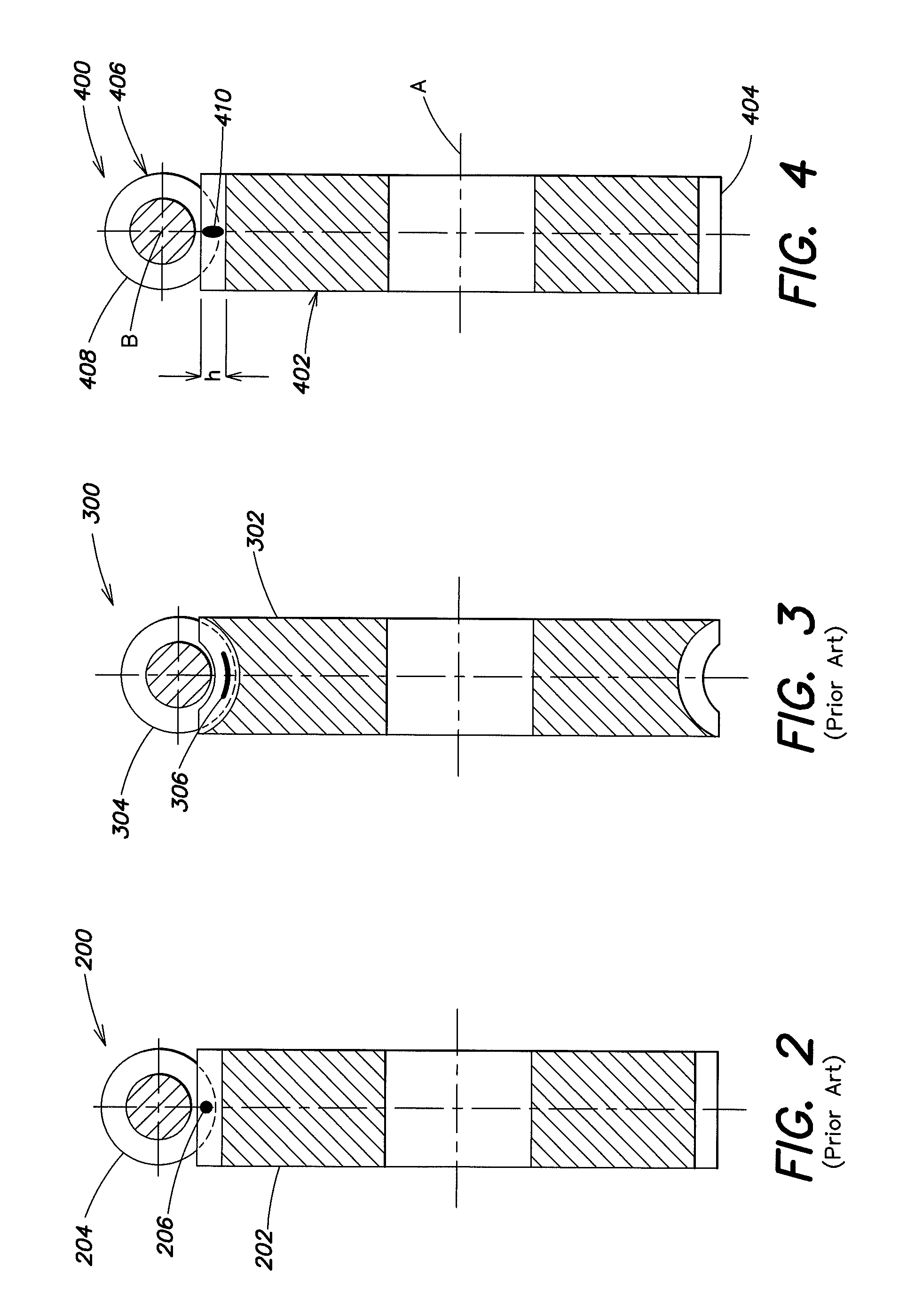
[0029]FIG. 4 illustrates a worm gear mechanism 400 in a section parallel to the rotation axis A of a worm gear 402. The worm gear 402 is cylindrical and has teeth 404 on its outer rim. A worm 406 rotates about an axis B that points perpendicularly to the drawing plane. The worm 406 is also cylindrical and has teeth 408 on its periphery. The teeth 404 of the worm gear 402 engage with the teeth 408 of the worm 406. The contact of the teeth 404 of the worm gear 402 with the teeth 408 of the worm 406 is identified as region 410. The contact region 410 extends substantially along height h of the teeth 404, 408 and is linear.

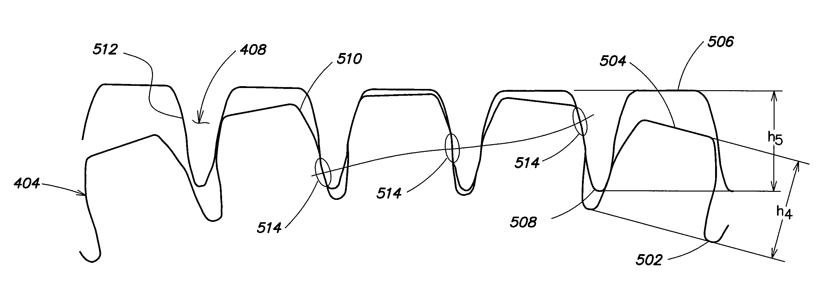
[0030]FIGS. 5A-5B illustrate the tooth geometry of the worm 406 and the worm gear 402 of FIG. 4. FIG. 5A shows the teeth 408 of the worm 406 pointing downward and the teeth 404 of the worm gear 402 pointing upward. The teeth 404, 408 engage with one another in this depiction as well. The teeth 404, 408 each have a height h4, h5, respectively. The height h4 extends fro...


PUM


Abstract

A power-assisted steering system includes a gear mechanism, coupled to a steering column, with a gear and a mating gear. The two transmission gears have teeth (4, 5) via which they engage with each other, movement and power being transmitted from one gear to the other gear via effective profiles of their tooth faces (11, 12). In order to provide a gear mechanism that has an enhanced load-bearing capacity and at the same time can be manufactured in a simple and economical way, the effective profiles of the tooth faces (11, 12) of the gear and the mating gear contact over the height (h4, h5) of the teeth (4, 5).

Description

BACKGROUND OF THE INVENTION[0001]The present invention relates to the field of steering mechanisms, and in particular to a power-assisted steering system having a gear mechanism with a gear and a mating gear.[0002]Power-assisted steering is regularly used in motor vehicles to assist with manual steering movements that a driver performs on the steering wheel. Power-assisted steering systems include hydraulics to minimize the steering forces and reduce steering, especially at low speeds or when the vehicle is stationary. Power-assisted steering improves driver comfort, especially in parking and maneuvering, and in city traffic. In addition, steering systems are being developed that are electrical rather than hydraulic systems.[0003]FIG. 1 is a pictorial illustration of a power-assisted steering system 100 with electromechanical steering assistance. FIG. 1 depicts a steering wheel 102 connected via a steering column 104 to a gear mechanism that has a worm gear 106 and a worm 108. In ad...

Claims


Application Information

Patent Timeline
IPC IPC(8): F16H35/00F16H1/16F16H1/20B62D5/04F16H55/08F16H55/22
CPCB62D5/0409Y10T74/19828F16H55/22
Inventor OBERLE, STEPHANENZMANN, BERND
Owner IMS GEAR GMBH
Why Eureka
Try Eureka