X-ray CT apparatus and a method of controlling the same

a ct apparatus and x-ray technology, applied in the field of x-ray ct apparatus, can solve the problems of difficult to make the x-ray ct apparatus more compact, difficult to achieve a simplification of the constitution and a reduction in manufacturing cost, and the regenerative resistance may reach a considerable temperature, etc., to achieve a large regenerative resistance, accumulate regenerative energy, and reduce the voltage

Active Publication Date: 2010-09-14
TOSHIBA MEDICAL SYST CORP
View PDF8 Cites 3 Cited by
  • Summary
  • Abstract
  • Description
  • Claims
  • Application Information

AI Technical Summary

Benefits of technology

[0029]The purpose of the present invention is to provide an X-ray CT apparatus that is capable of making effective use of the regenerative energy that has accumulated in the regenerative resistance with a simple and compact constitution as well as a method of controlling the same.
[0036]According to the first and third modes, it becomes possible to lower the voltage of and accumulate regenerative energy. This eliminates the need for releasing heat and thus the need to install a large regenerative resistance, so the capacity of the accumulation part can be made smaller. Therefore, it is possible to simplify the constitution of the X-ray CT apparatus and to make the apparatus more compact. In addition, because the accumulated regenerative energy is used for driving the rotating body, the reuse of energy can contribute to energy saving.
[0037]According to the second and fourth modes of the present invention, it becomes possible to use regenerative energy without change for other mechanisms in the X-ray CT apparatus, such as a bed drive part or a console. This eliminates the need for accumulating the regenerative energy, thereby making it possible to be more compact. In addition, because the regenerative energy is used for other mechanisms, the reuse of energy can contribute to energy saving.

Problems solved by technology

Therefore, when the motor frequently accelerates / decelerates, such as when consecutively imaging multiple subjects or when a service engineer performs maintenance or the like, the regenerative resistance may reach a considerable temperature.
Meanwhile, for an X-ray CT apparatus in which it is difficult to ensure a sufficient space for installing the regenerative resistance on the upper portion of a mounting base, the lateral portion of the apparatus is often provided with the regenerative resistance.
However, the development of X-ray CT is currently moving in the direction of reducing the burden on a subject by shortening the imaging time.
In other words, a so-called air-cooled heat releasing function described in Patent Documents 1 through 3 requires a large-capacity regenerative resistance for the release of heat energy increased by the accelerated rotation of the rotating body, thereby making it difficult to achieve a simplification of the constitution and a reduction in the manufacturing cost.
In addition, for the technology described in Patent Document 4, it is difficult to make the X-ray CT apparatus more compact, because regenerative energy is accumulated without change and the capacity of the accumulating portion thus becomes larger.

Method used


Image

  • X-ray CT apparatus and a method of controlling the same
  • X-ray CT apparatus and a method of controlling the same
  • X-ray CT apparatus and a method of controlling the same

Examples


embodiment 1

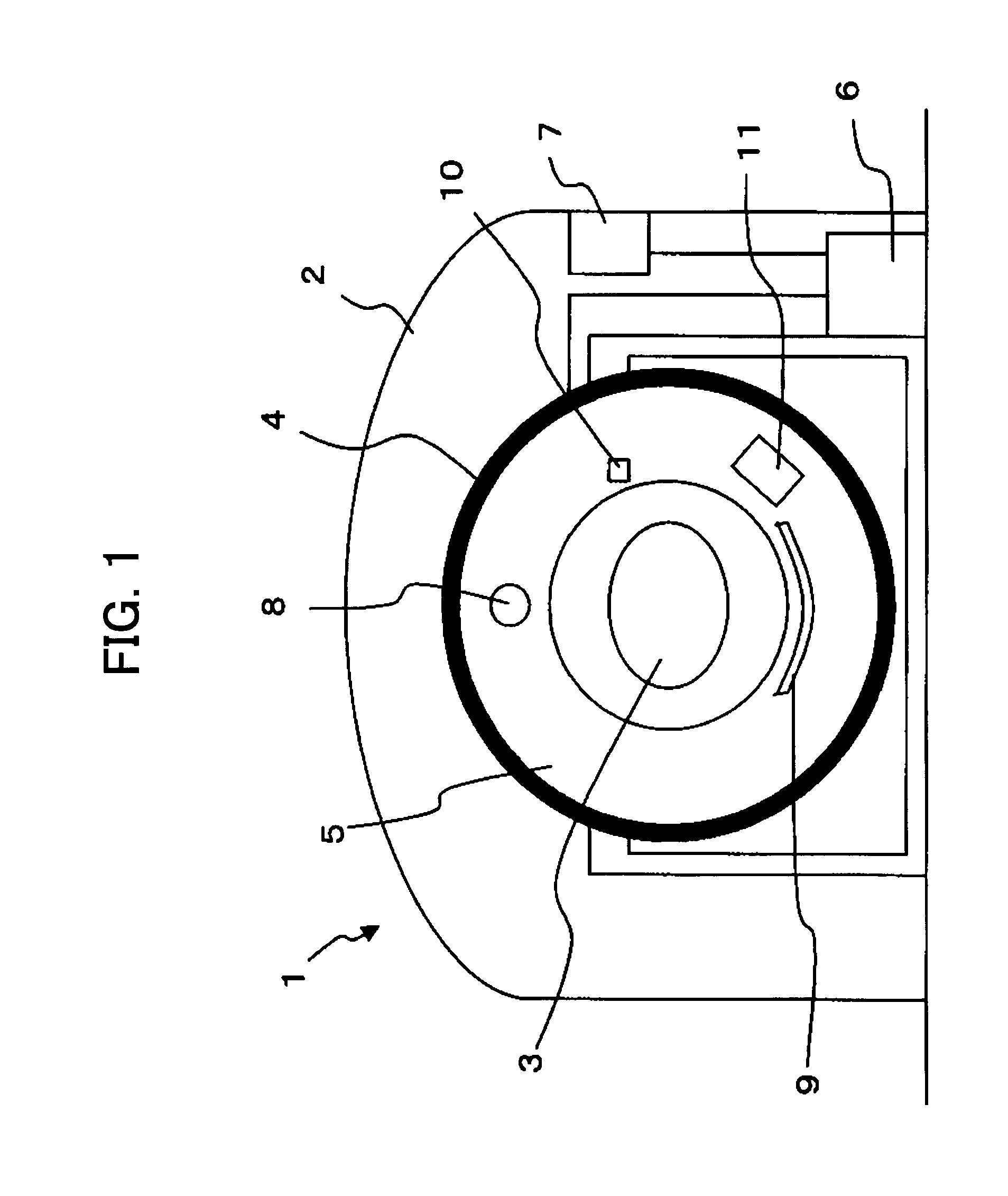
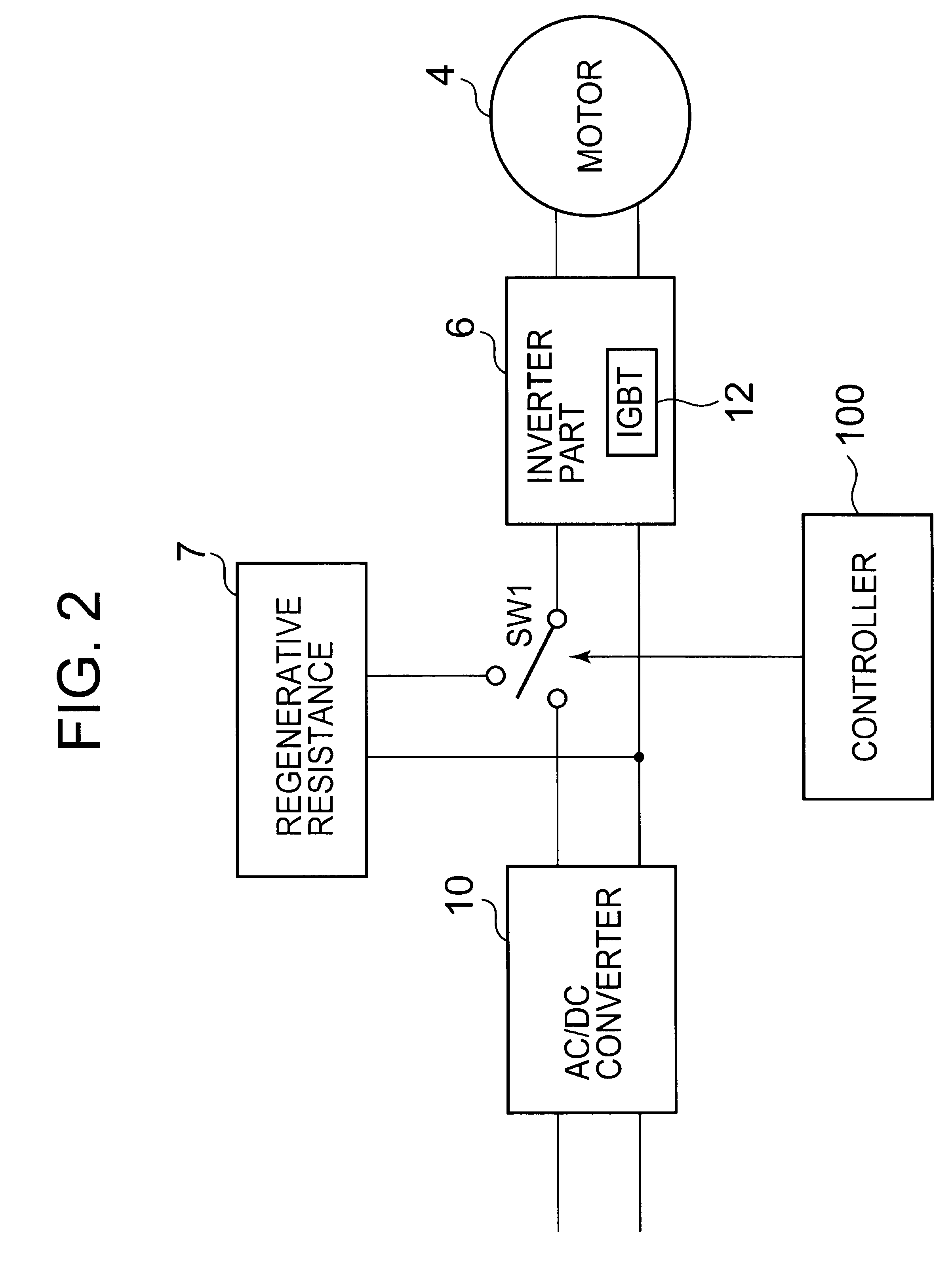
[0045]Hereinafter, an X-ray CT apparatus according to the first embodiment of the present invention will be described. FIG. 3 is a block diagram representing the functions of the X-ray CT apparatus according to the present embodiment. The operator performs the setting of the X-ray irradiation and the like by using a console (not shown) or the like.

[0046]The AC / DC converter 10 is connected to the motor 4 via the inverter part 6. The AC / DC converter 10 converts the electrical power of a three-phase AC voltage from a commercial power source (alternating-current voltage) into DC voltage (direct-current voltage) electrical power and conveys the same to the inverter part 6. Herein, the AC / DC converter 10 is equivalent to the “power source” in the present invention.

[0047]The inverter part 6 comprises switching elements such as IGBTs.

[0048]During rotary driving of the rotating body 5, the switching elements are controlled so as to supply electrical power from the side of the AC / DC converter...

embodiment 2

[0075]Hereinafter, an X-ray CT apparatus according to the first embodiment of the present invention will be described. FIG. 5 is a block diagram representing the functions of the X-ray CT apparatus according to the present embodiment. Herein, in FIG. 5, one represented by the identical number to that in FIG. 3 shall represent one having an identical function. The operator sets the X-ray irradiation conditions, scanning conditions, image warping conditions, and the like by using a console (not shown) or the like.

[0076]The step-up part 201 comprises a transformer or the like. The step-up part 201 raises the entered voltage to the prescribed voltage.

[0077]The step-up part 201 conveys the electrical power of the raised voltage to the AC / DC converter 10.

[0078]For rotary driving of the rotating body 5, the AC / DC converter 10 converts the AC voltage conveyed from the step-up part 201 into a DC voltage. Then, the AC / DC converter 10 conveys the DC voltage to the inverter part 6. In addition,...

embodiment 3

[0100]The X-ray CT apparatus according to the present embodiment differs from the first embodiment in that it is configured to supply the electricity accumulated in the accumulation part to another structural unit such as an image-processing apparatus, a bed drive part, or a console. Then, hereinafter, the constitution and operations for supplying the electrical power accumulated in the accumulation part to another structural unit will mainly be described. The block diagram of the X-ray CT apparatus according to the present embodiment is a functional block of the X-ray CT apparatus according to the first embodiment shown in FIG. 1 to which a functional block represented by dotted lines has been added.

[0101]The Electric Double Layer Capacitor 101 is connected to the step-up chopper 103 and the voltage-transforming part 301 as destinations of the power supply.

[0102]Then, the electrical power accumulated in the Electric Double Layer Capacitor 101 is supplied to the voltage-transforming...


PUM


Abstract

An X-ray-generator irradiates X-rays at a subject. The X-ray-detector detects the X-rays that have permeated the subject. The rotating body on which the X-ray-generator and the X-ray-detector are installed rotates around the subject. The rotating body is rotated by the drive part. The power source supplies electrical power to the drive part. The step-down part lowers the voltage of the regenerative electrical power generated at the drive part during the deceleration of the rotating body. The accumulation part charges the lowered electrical power. The step-up part raises the voltage of the electrical power from the accumulation part and supplies electrical power to the drive part.

Description

BACKGROUND OF THE INVENTION[0001]1. Field of the Invention[0002]The present invention relates to an X-ray CT apparatus that reuses regenerative energy and a method of controlling the same.[0003]2. Description of the Related Art[0004]In the field of an X-ray computer tomography apparatus (an X-ray CT apparatus) that performs tomography of a subject by using X-rays, efforts have been made on a daily basis in various aspects such as the facilitation of multifunctionality, sophisticated performance, and the shortening of imaging time. However, the amount of heat that is released tends to increase as the performance and functionality of these apparatuses improves.[0005]As such technological innovation advances, the issue of how to externally release the heat that is generated as a byproduct inside the apparatus has been studied in conjunction.[0006]A representative of the heat generated inside the X-ray CT apparatus is attributable to the regenerative resistance. Regenerative resistance ...

Claims


Application Information

Patent Timeline
Patent Type & Authority Patents(United States)
IPC IPC(8): H05G1/24
CPCA61B6/032A61B6/56A61B6/4488
Inventor KASUYA, YUICHI
Owner TOSHIBA MEDICAL SYST CORP
Why Eureka
Try Eureka