
Methods of producing diffractive structures in security documents

a technology of diffractive structures and security documents, applied in the direction of printing processes, holographic processes, decorative arts, etc., can solve the problems of high cost, complex and highly specialised process required to produce multi-layer optical diffractive device structures, and may contain at least four and often more layers

Inactive Publication Date: 2010-09-07
CCL SECURE PTY LTD
View PDF58 Cites 4 Cited by
  • Summary
  • Abstract
  • Description
  • Claims
  • Application Information

AI Technical Summary

Benefits of technology

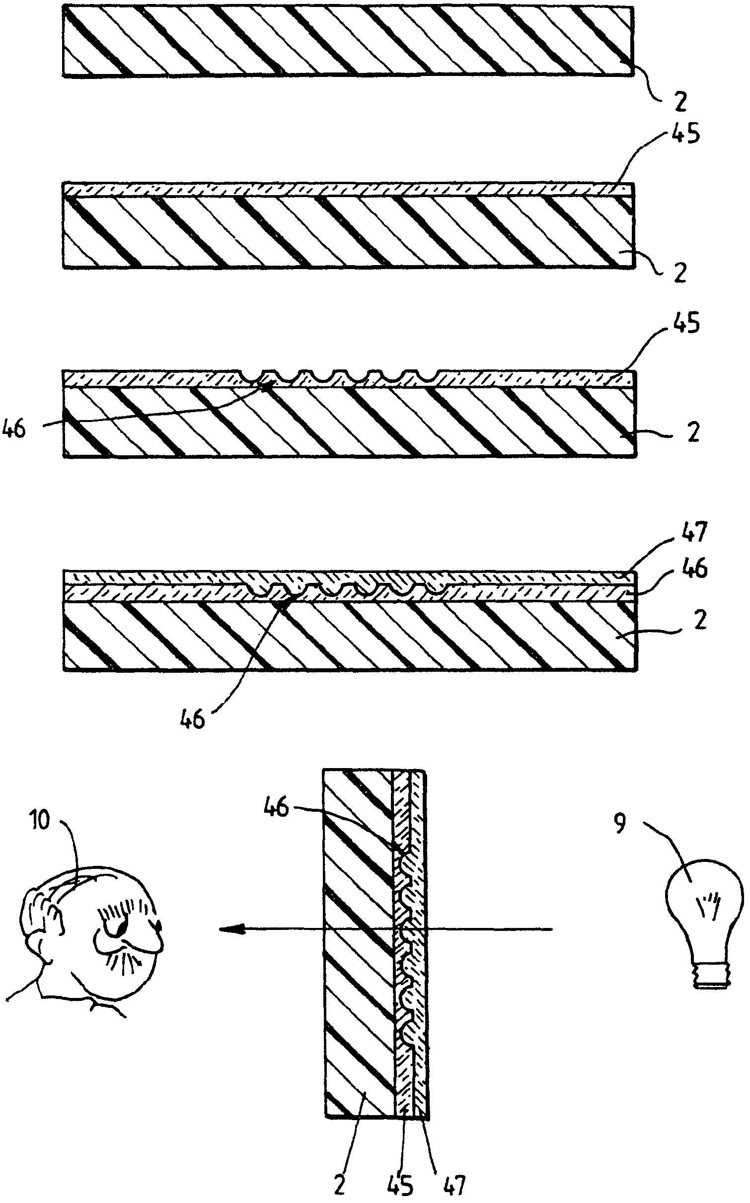
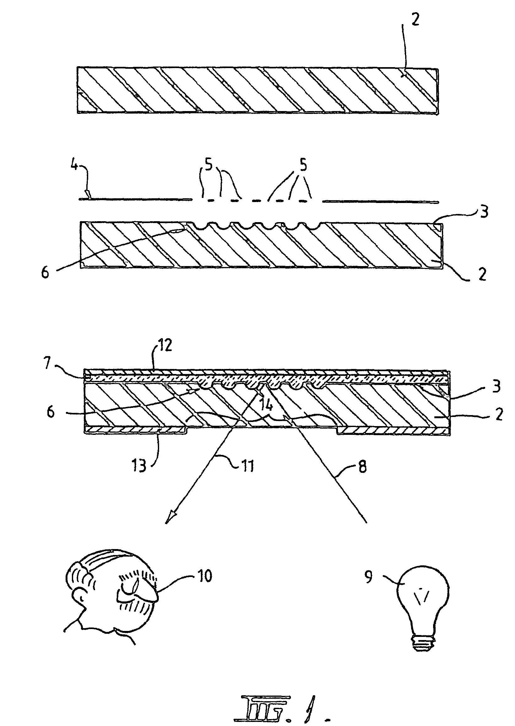
[0009]The present invention significantly simplifies the multi-layered structure of a security device when incorporated into the security document or device. The application of an optically diffractive device may be easily integrated into the process of manufacture of the security document or device. Moreover, in those cases in which reflective optically diffractive devices are used, it is possible to eliminate the use of a brittle metallised coating.
[0026]Accordingly, a single mask may be provided for use in the production of security documents or similar articles that results in the rapid and repeatable generation of a fixed diffractive structure in the articles produced. The mask may be manufactured such that the diffractive structure generates any desired image, such as an image individual to, or distinctive of, a producer or issuer of a security document. The resulting diffractive structure may then be used, for example, to authenticate security documents originating from a particular source.
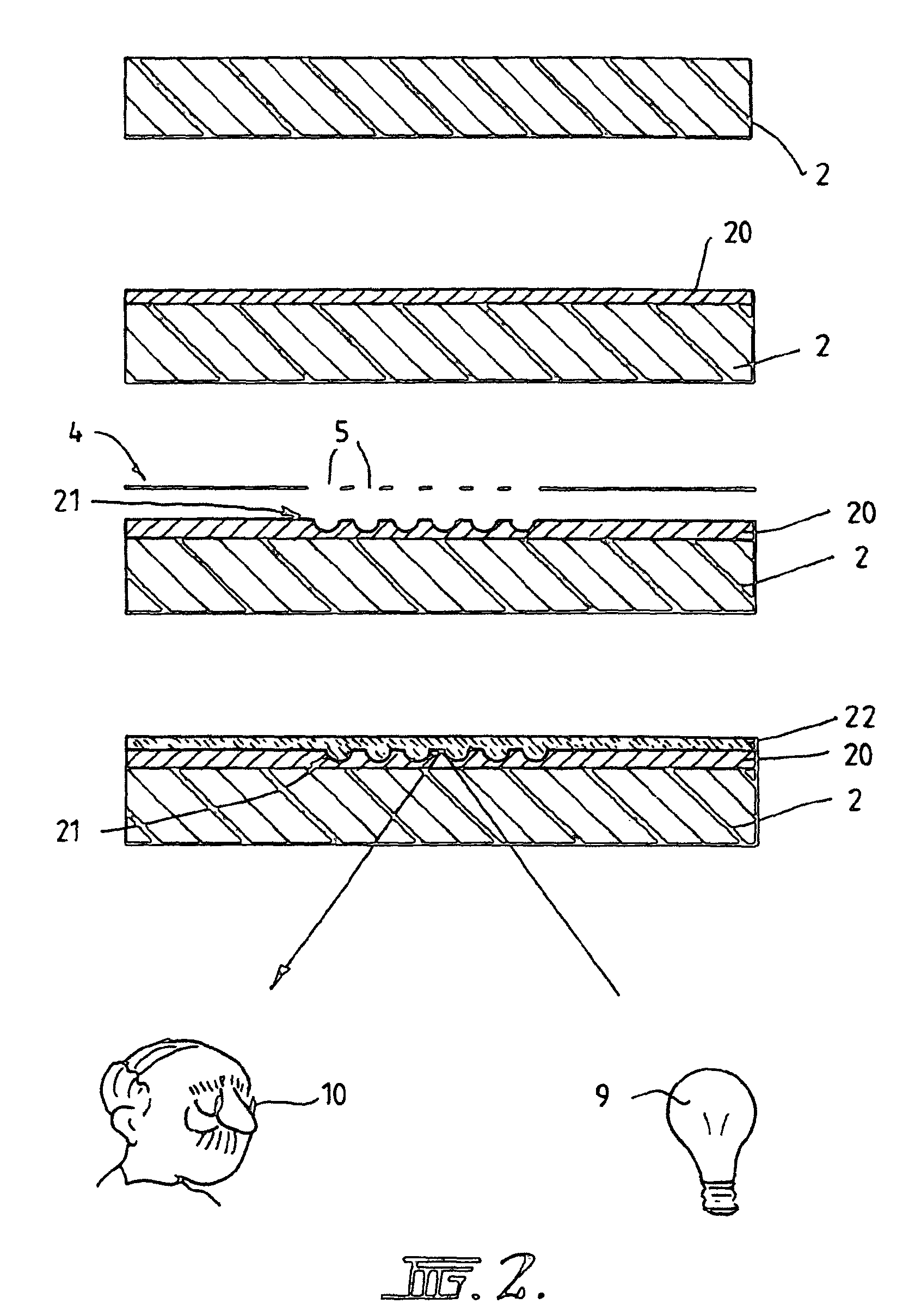
[0031]The opacifying layer is preferably a stronger absorber of laser radiation than the substrate. The wavelength of the laser radiation may be selected such that when the article is exposed to the radiation, the selected portions of the opacifying layers absorb the radiation and are ablated from the substrate, the substrate being substantially transparent to the radiation at the selected wavelength so that the laser radiation travels through the substrate without significant absorption. Accordingly, the opacifying layer may be ablated by the laser radiation without damage to the substrate.
[0043]In this aspect of the invention, the selected portions of the opacifying layer which are ablated by the laser radiation may not extend completely through the opacifying layer. In this manner, it is possible to form a reflective diffractive optical microstructure, eg a hologram, in the surface of the opacifying layer. However, because the microstructure is formed in the surface of the opacifying layer adjacent to the transparent substrate, the diffractive optical effects produced by the microstructure are substantially unaffected by subsequent application of a coating or laminate over the opacifying layer.

Problems solved by technology

A number of disadvantages are associated with the production and application of optically diffractive and other devices in this manner.
Firstly, the complex and highly specialised process required to produce the multi-layer optically diffractive device structure, which may contain at least four and frequently more layers, is costly.
Secondly, an extra process step is required to transfer the optically diffractive device from the carrier substrate onto the security document or device.
Thirdly, the resistance of the optically diffractive device as a whole to physical wear and tear and chemical attack is poor due to the weakness of the vacuum metallised reflective layer.

Method used


Image

  • Methods of producing diffractive structures in security documents
  • Methods of producing diffractive structures in security documents
  • Methods of producing diffractive structures in security documents

Examples


Embodiment Construction

[0056]Referring now to FIG. 1, there is shown a transparent plastics film 2 formed from polymeric material, used in the manufacture of polymer banknotes. The substrate 2 may be made from at least one biaxially oriented polymeric film. The substrate may comprise a single layer of film of polymeric material, or, alternative, a laminate of two or more layers of transparent biaxially oriented polymeric film. The substrate 2 is seen in cross section in FIG. 1. Whilst the invention will be described with reference to FIGS. 1 to 6 in relation to the production of polymer banknotes, it is to be appreciated that the invention may also be used in the production of credit cards, cheques and other security documents or devices, and that the function and properties of the substrate in those security documents or devices may vary.

[0057]In this example, a diffraction grating or other optically diffractive device is formed on one surface 3 of the substrate 2 by irradiating an area of that surface w...


PUM

PropertyMeasurementUnit
Microstructureaaaaaaaaaa
Areaaaaaaaaaaa
Metallic bondaaaaaaaaaa

Abstract

Various methods of producing a security document or article including a diffractive optical microstructure are disclosed. One method includes applying an opacifying layer (102) to at least one surface of a transparent substrate (100). An area of the opacifying layer (102) is exposed to laser radiation (108) to ablate apertures (110) in selected portions of the opacifying layer (102), thereby forming a diffractive optical microstructure (112) on the surface of the substrate (100). The laser radiation may be patterned prior to exposing the opacifying layer (102), for example by passing the radiation through a mask (104). Alternatively, a focussed or collimated laser beam (206) may be directed onto the selected portions of the opacifying layer (102). Laser radiation may be directed onto the opacifying layer (102) either directly, or through the transparent substrate (100). Security documents or articles made in accordance with the method are also provided.

Description

CROSS REFERENCE TO RELATED APPLICATION[0001]The present application is a continuation-in-part application of U.S. patent application Ser. No. 10 / 019,086, filed Apr. 9, 2002, now abandoned which application is the U.S. national stage application of International Application No. PCT / AU00 / 00726, filed Jun. 27, 2000. The International Application was published on Jan. 4, 2001 as International Publication WO 01 / 00418 in the English language. The International Application claims the priority of Australian Patent Application No. PQ 1259, filed Jun. 28, 1999. This application also claims priority of Australian Provisional Application No. 2004903948, filed Jul. 16, 2004.BACKGROUND OF THE INVENTION[0002]The present invention relates generally to methods of producing a security document or device, and in particular to security documents or device which include an optically diffractive structure, such as a diffraction grating or like device. The invention is applicable to the production of bank...

Claims


Application Information

Patent Timeline
IPC IPC(8): G03H1/02G02B5/18B23K26/00B41M3/14B41M5/24B42D15/00B42D15/10B42D25/00B42D25/29B42D25/328B42D25/41B42D25/42B44F1/12G08B13/187
CPCB41M3/14B42D25/00B41M5/36G03H1/0276B42D25/41B42D25/42B42D25/29B42D25/328B41M5/24B42D2035/20B42D2035/26G03H1/0011G03H1/0244G03H2001/0292G03H2260/62B42D25/309B42D25/324B42D25/351B42D25/313B42D25/435B42D25/373G03H1/02
Inventor ZIENTEK, PAULPOWER, GARY FAIRLESSNEMETH, JOSHUA ROBERT
Owner CCL SECURE PTY LTD
Learn More