Plasma display panel having laminated members and visible light reflection layer

a technology of plasma display panel and visible light reflection layer, which is applied in the direction of electrodes, identification means, instruments, etc., can solve the problems of reduced light-room display contrast ratio and difficult fabrication of high-barrier ribs, so as to suppress the degradation of display luminance, improve luminous efficacy, and improve display contrast. effect of plasma display panel

Inactive Publication Date: 2010-08-24
MAXELL HLDG LTD
View PDF17 Cites 3 Cited by
  • Summary
  • Abstract
  • Description
  • Claims
  • Application Information

AI Technical Summary

Benefits of technology

[0015]It is an object of the present invention to improve display contrast of a plasma display panel and to suppress degradation in display luminance and improve luminous efficacy at the same time.
[0016]In the case of the ac surface-discharge type, since the discharge for producing a display is generated along a surface, improvement of luminance and luminous efficacy requires an increase in the discharge space. The discharge space can be made larger by increasing its aperture ratio, where the aperture ratio is defined as a ratio of an area of a window portion of the front substrate through which display-forming visible light is irradiated into the viewing space, that is, an area of an aperture, to an area of a projection of the display discharge space onto the display surface. However, an increase in the aperture ratio decreases an area usable for a black matrix which fills spaces between the apertures with black opaque material, and a problem arises in that a light-room display contrast ratio is reduced.
[0038]The structures in accordance with the present invention are capable of realizing a high-contrast plasma display panel with degradation in display luminance being suppressed.

Problems solved by technology

However, an increase in the aperture ratio decreases an area usable for a black matrix which fills spaces between the apertures with black opaque material, and a problem arises in that a light-room display contrast ratio is reduced.
However, in that case, the height of barrier ribs surrounding the discharge space needs to be selected to be greater, and consequently, it makes fabrication of the high barrier ribs difficult by using a process which fabricates the barrier ribs on the front or rear plate.

Method used


Image

  • Plasma display panel having laminated members and visible light reflection layer
  • Plasma display panel having laminated members and visible light reflection layer
  • Plasma display panel having laminated members and visible light reflection layer

Examples


example 1

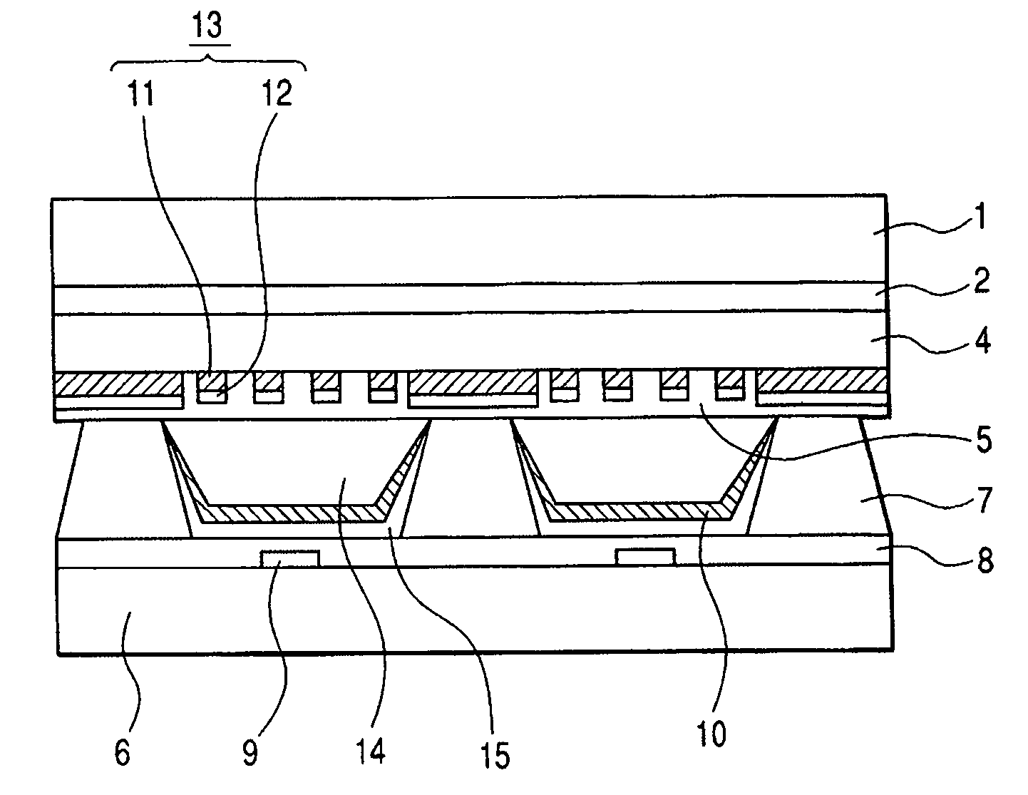
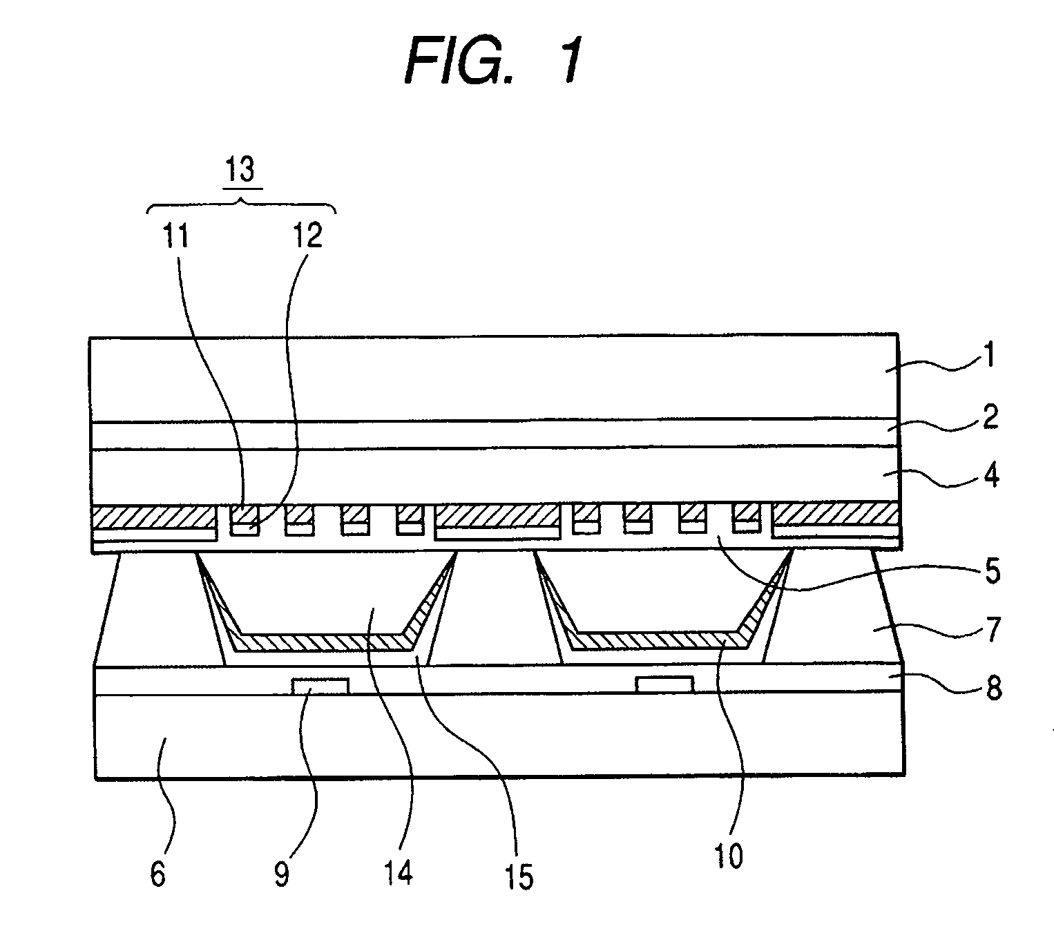
[0122]FIG. 14 is a front view of a structure of a plasma display panel in accordance with Example 1, FIG. 15 is a cross-sectional view of the structure of FIG. 14 taken along line Y-Y1 of FIG. 14, and FIG. 16 is a cross-sectional view of the structure of FIG. 14 taken along line X-X1 of FIG. 14.

[0123]After electrodes 2 and 3 were fabricated on the front substrate, the laminated members 13 comprised of the light absorption layer 11 and the light reflection layer 12 were fabricated. The light absorption layers 11 were made of chromium oxide.

[0124]Initially, a paste composed of chromium oxide particles, low-melting glass powders, a binder and a solvent is prepared for the light absorption layers 11. The paste is coated on the substrate by using a screen printing method, and then the solvent was volatilized by drying the paste. Next, the light reflection layers 12 made of titanium oxide were fabricated. Initially, a paste composed of titanium oxide particles, low-melting glass powders, ...

example 2

[0127]FIG. 18 is a front view of a structure of a plasma display panel in accordance with Example 2, FIG. 20 is a cross-sectional view of the structure of FIG. 18 taken along line X-X′ of FIG. 18, and FIG. 19 is a cross-sectional view of the structure of FIG. 18 taken along line Y-Y1 of FIG. 18. The plasma display panels of Example 2 were fabricated in the same way as Example 1, except that the laminated members 13 comprised of the light absorption layer 11 and the light reflection layer 12 are disposed on the surface of the layer of the dielectric 4, and their display luminance was measured.

[0128]The plasma display panels of Example 2 have exhibited improvement in luminance over the above-described comparative examples with their aperture ratios being in a range of from 0.1 to 0.8, and an improvement in luminance was realized by dispersing the laminated members 13 comprised of the light absorption layer 11 and the light reflection layer 12 within each of the discharge cells.

example 3

[0129]This example is similar to Example 1, except that the laminated members 13 comprised of the light absorption layer 11 and the light reflection layer 12 were integrally fabricated to form a unitary structure perforated with plural openings as illustrated in FIG. 8(b). The display luminance of the fabricated plasma display panels of Example 3 was measured.

[0130]The plasma display panels of Example 3 have exhibited improvement in luminance over the above-described comparative examples with their aperture ratios being in a range of from 0.1 to 0.8, and an improvement in luminance was realized by dispersing the laminated members 13 comprised of the light absorption layer 11 and the light reflection layer 12 within each of the discharge cells.


PUM


Abstract

A plasma display panel has plural discharge cells between two opposing first and second substrates. Each of the discharge cells includes at least one pair of electrodes for generating a discharge for display, a discharge gas and a phosphor film for emitting visible light by being excited by ultraviolet rays produced by the discharge of the discharge gas. Laminated members are dispersed in a plane within each of the discharge cells inside the first substrate from which visible light for display is emitted, and each of the laminated members includes a light absorption layer disposed on a side of the first substrate on which ambient light is incident and a light reflection layer disposed on a phosphor-film side of the laminated members. A visible-light-reflection layer is disposed on a surface of the phosphor film on a side thereof opposite from a space in which the discharge is generated.

Description

CLAIM OF PRIORITY[0001]The present application claims priority from Japanese application serial no. 2005-189377, filed on Jun. 29, 2005, the content of which is hereby incorporated by reference into this application.BACKGROUND OF THE INVENTION[0002]1. Field of the Invention[0003]The present invention relates to a plasma display panel (hereinafter also referred to as a PDP) used for a flat-type TV set and others and a plasma display device employing the plasma display panel, and in particular to a structure of a plasma display panel capable of realizing the improvement of its display luminance and display contrast.[0004]2. Description of Prior Art[0005]The plasma display panel is used in a large-screen, small-depth, flat-screen TV set, and has improved in performance. However, its light-room display contrast, that is, a contrast as measured in a well-lighted environment (usually assumed to be a living room provided with an ambient room illumination producing 150-200 lx), is not satis...

Claims


Application Information

Patent Timeline
Patent Type & Authority Patents(United States)
IPC IPC(8): H01J17/49H01J11/12H01J11/22H01J11/24H01J11/26H01J11/34H01J11/36H01J11/38H01J11/40H01J11/42H01J11/44H01J11/50
CPCH01J11/12H01J11/44H01J2211/442G09F9/313H01J17/492
Inventor MIYAKE, TATSUYASUZUKI, KEIZOSHIIKI, MASATOSHIOKAZAKI, CHOICHIROFUJITA, TSUYOSHITSUCHIDA, SEIICHI
Owner MAXELL HLDG LTD
Why Eureka
Try Eureka