
Electrical apparatus having quick connect components

a technology of electric apparatus and components, applied in the direction of coupling device connection, tumbler/rocker switch details, containers, etc., can solve the problems of increasing the probability of wiring errors in the field, adding to the complexity of industry standardization issues, inconsistent results and errors, etc., to bring a level of standardization, modular connectivity, and safety

Inactive Publication Date: 2010-08-03
THE WEST END DESIGN GROUP
View PDF54 Cites 58 Cited by
  • Summary
  • Abstract
  • Description
  • Claims
  • Application Information

AI Technical Summary

Benefits of technology

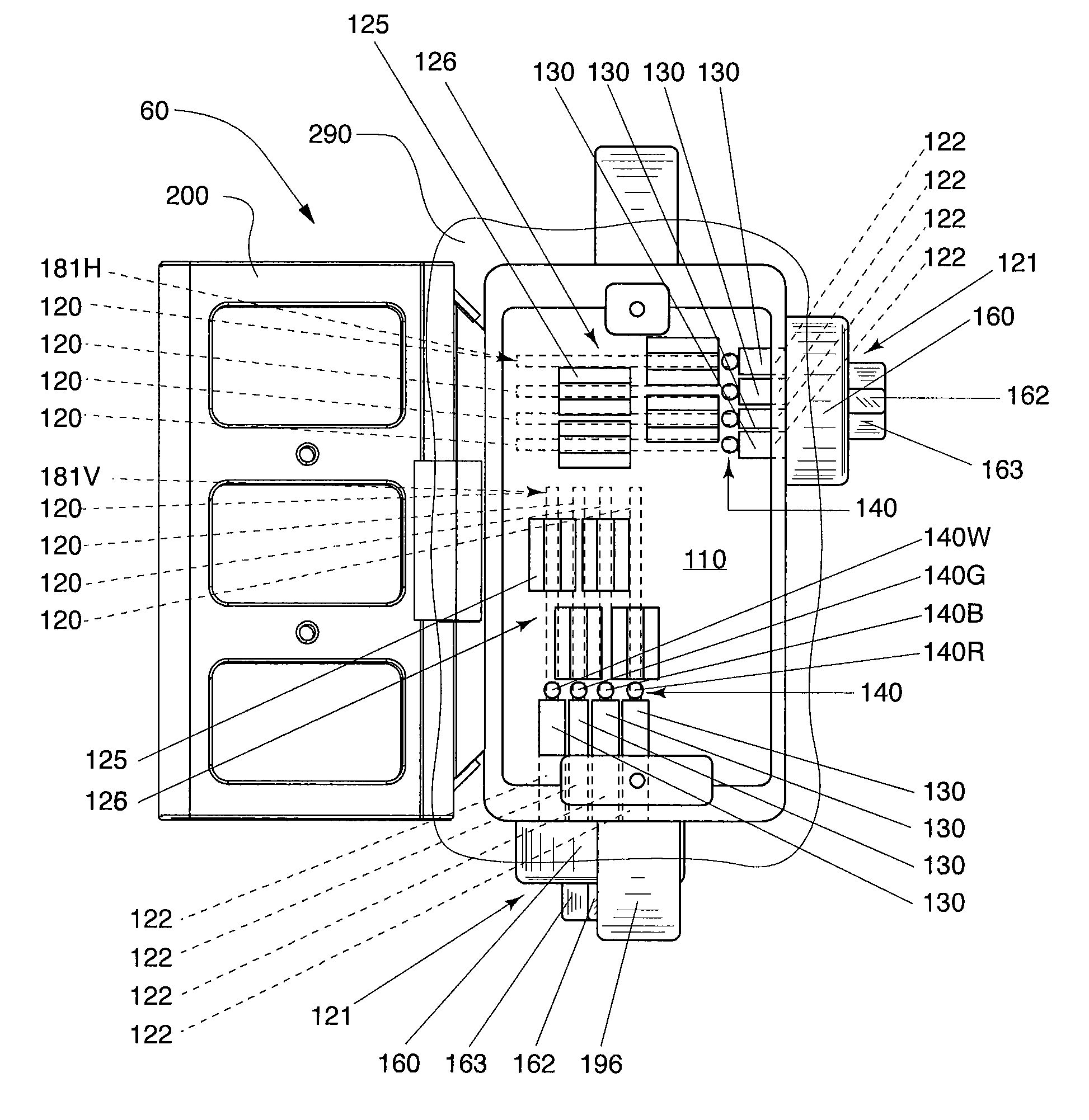
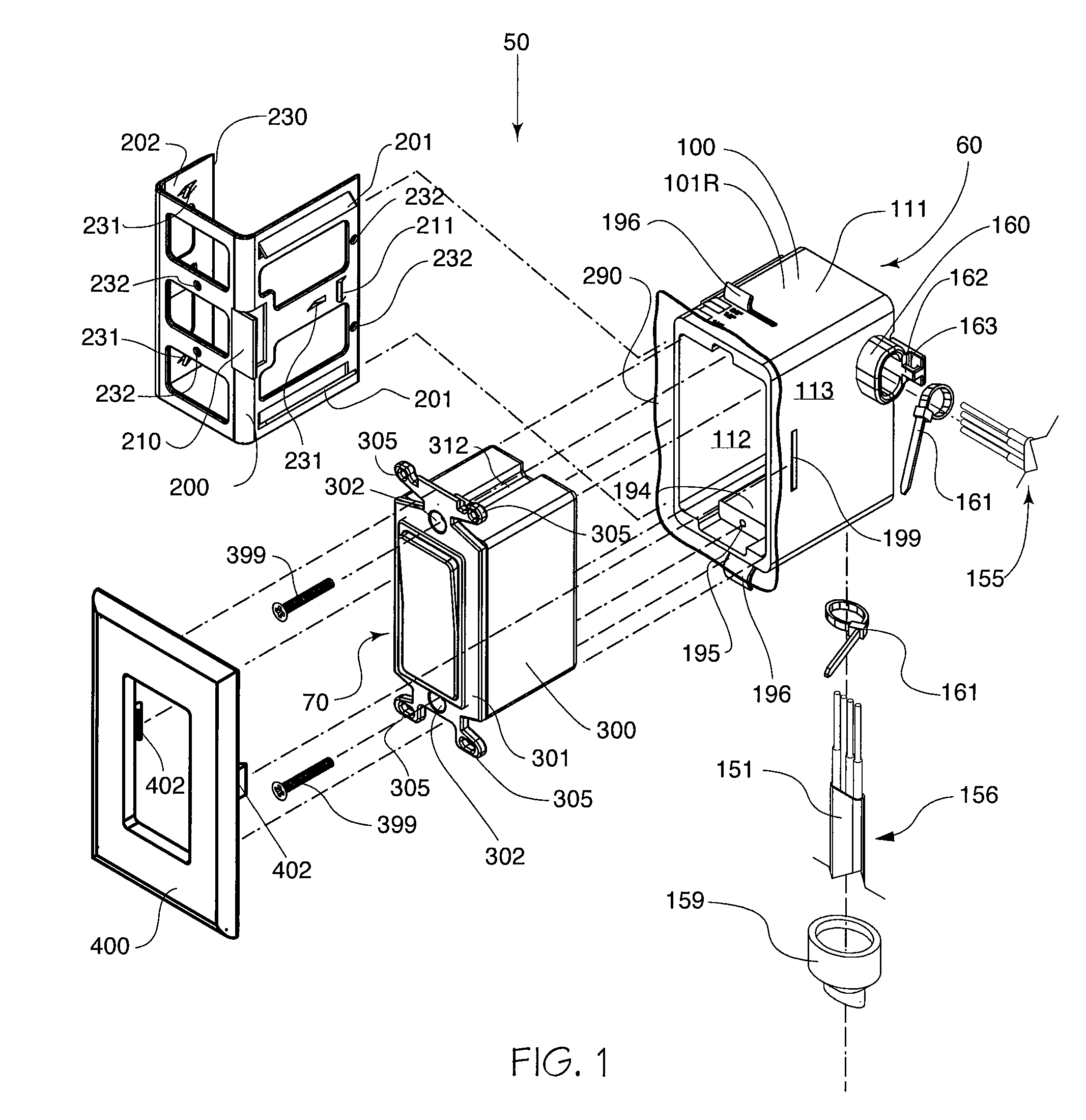
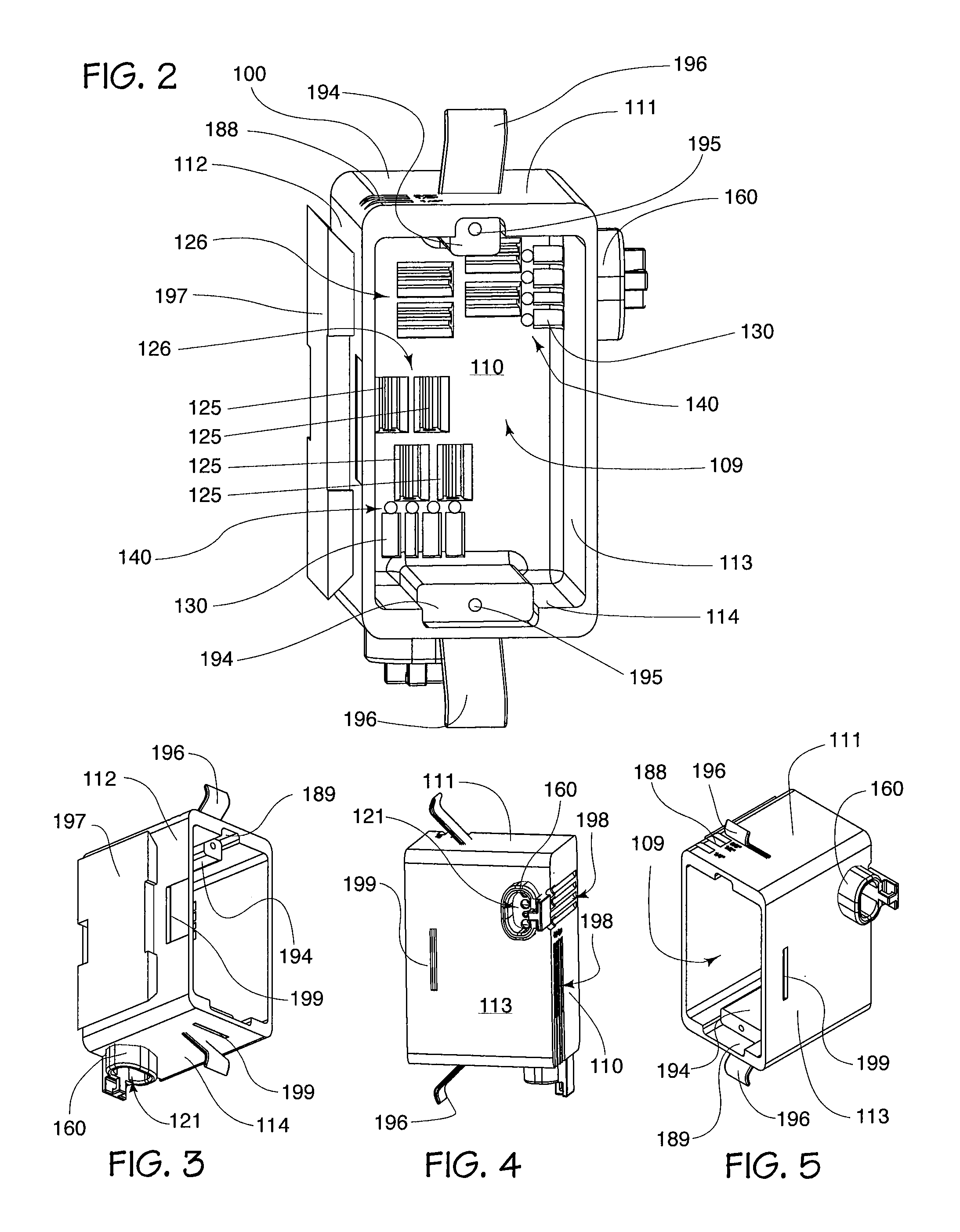
[0023]Accordingly, several objects and advantages of the present invention include the design and establishment of methods and / or apparatuses that can set an industry standardization base line for connections to an electrical distribution system. This level of stylization will allow all manufacturers to continue to produce their current line of electrical devices, yet enjoy the advantages of modular connectivity of their product line into a universal electrical box. It is an advantage of embodiments of this invention that modular connectivity will provide a tremendous benefit to the industry with respect to labor cost savings, safety, speed, and accuracy. While this invention is broad, one only has to think back to the popularity of the fuse box prior to the introduction of the circuit breaker and its associated panel. The circuit breaker revolutionized the electrical industry by bring a level of standardization, safety, and modular connectivity to an entire industry.
[0024]It is another object of the present invention to reduce the skill, experience, and knowledge required to proficiently and safely wire the multitude of electrical devices in an average home. An advantage is the simplicity of ‘Plug-and-Play’ operability. In aspects of the invention, the devices are ‘hot-swappable’ and a homeowner can even safely and quickly change a light toggle switch to a dimmer switch without even turning the power off. Even a novice can install a three-way switch by simply acquiring two three-way switches.

Problems solved by technology

This multiplicity has produced a wide variety of connection standardization issues.
These issues are compounded by the requirement that many of these components must be wired in several different ways, even within the same circuit, to produce a specific desired outcome.
This diverse conglomeration of wiring schemes and connection methods adds to the complexity of industry standardization issues.
Previously this lack of connection standardization would increase the probability of wiring errors in the field.
Knowledge of code requirements and best practice procedures tend to differ widely between installers, thus producing inconsistent results and errors.
These wiring errors range from burdensome inconveniences to life threatening safety issues.
Even minor field wiring errors would impact both the safety and the profitability of every job.
Hand wiring requires the expensive services of electricians utilizing procedures that differ only slightly from the procedures in use for over fifty years.
Hand wiring is extremely time-consuming and since the hourly wage of electricians is among the highest of all craftsmen, the cost of installing the electrical distribution system in a building represents a substantial portion of the total building cost.
This problem has been partially solved by the implementation of some specific function devices, but these devices still have significant problems and all of them fail to address the needs of the entire industry.
In addition, all previous attempts to invent pre-wired junction boxes have been complicated and expensive, as exemplified in U.S. Pat. Nos. 6,201,186; 5,525,754; 4,336,418; and 4,165,443.
Previously the number of connections that had to be made and housed within the box determined the interior size of the electrical box, compounding the complexity of industry standardization issues.
Over time, this scrap would equate to a considerable expense, considering the amount of connections required during a typical construction project and the ever rising cost of copper.
While twist-on wire connectors work well when joining two like wires, they are less reliable and more difficult to use in joining wires of differing gauges and construction.
This was a significant cost in time and materials.
Previously connections that were sound in a static condition would often become compromised when the wires were twisted, turned, and compressed into their electrical box.
Those compromised connections would commonly fail and tend to go unnoticed until electrical power was established.
This added step would come at a cost of both time and resources.
A troubleshooting regiment would require a period of operation in a potentiality unsafe condition.
It was not practical, from a time and resources point of view, to inspect each electrical box for correct and sound wiring connections.
In fact, the process of pulling a switch from its electrical box for inspection and then replacing it could, in itself, be the cause of a connection failure.
Previously the interior of the connection boxes and all wires within could become contaminated by sheetrock material, dust, and other construction debris.
The wires would become contaminated further by overspray when the wall texture was sprayed on the walls and yet again when the paint was sprayed or rolled onto the walls and ceilings.
This would result in a significant amount of time being spent by the electrician to clean out the electrical box, as well as each individual wire in the box.
Previously, once the sheetrock was in place, the electrician would not be able to visually identify which wire would lead to which location.
This was time consuming and a daunting task for less experienced installers.
Previously, both the professional and amateur electrician often experienced difficulty in connecting devices with stranded wire leads to solid stiff wire leads.
Soldering and pre-taping the wires was time consuming and was therefore rarely used.
These interconnections commonly failed as the wires were compressed and forced into the confined space of a traditional electrical box.
Previously a common problem would present itself when the electrical box was not properly secured to its respective supporting stud or other support.
In addition, secure electrical boxes often become loose when their respective electrical wires were pushed, pulled, twisted, and compressed within the box.
Another common problem presented itself when the secure fit of an electrical box was compromised during the sheetrock process.
They can be knocked askew and become less secure in the process.
Proper stabilization of the now compromised electrical box would typically require removal of the sheetrock, greatly disfiguring the area around the box, and is very labor-intensive and time consuming.
Unfortunately, this has given rise to a common field practice whereby the electrician will attempt to semi-secure the electrical box by simply compressing the sheetrock between the switch head and the electrical box and then covering the evidence of a code violation with the faceplate.
While this method is less desirable, it is quick and prevents the removal of the sheetrock to reattach the electrical box.
Previously another problem was manifested when an electrical box was attached to the supporting stud too far back into the wall cavity, thus leaving an unacceptable space between the electrical box and the faceplate.
While this was not as dangerous as the previous example, it was visually unappealing for the end user.
This action would further compromise the security of the electrical box and could damage the wire and components housed within the electrical box.
Electrical connections were often compromised as the switches were shoved and twisted within the electrical box while seeking this proper alignment.
A quad-switch electrical box would typically require eight small screws to secure it into position, requiring the cost of the screws and the cost of the electrician's time to align the switches and screw in the screws.
An error could result in physical harm.
However, these prior art devices are typically application specific and can actually make the installers job more complex and, at times, more confusing.
The electrical boxes from all of these patents have, among other things, multiple internal parts comprising sandwiched bus bar or bus plate assemblies with insulating spacers, thus requiring an increased cost and significant manufacturing and assembly requirements.
By way of non-limiting example, they only support a limited number of electrical devices specifically designed to fit their unique electrical box, and / or exclude many other devices currently under production by manufacturers around the world.

Method used


Image

  • Electrical apparatus having quick connect components
  • Electrical apparatus having quick connect components
  • Electrical apparatus having quick connect components

Examples


Embodiment Construction

[0202]As used herein, the use of the word “a” or “an” when used in conjunction with the term “comprising” (or the synonymous “having”) in the claims and / or the specification may mean “one,” but it is also consistent with the meaning of “one or more,”“at least one,” and “one or more than one.” In addition, as used herein, the phrase “connected to” and the like means joined to or placed into communication with, either directly or through intermediate components.

[0203]In one embodiment, this invention introduces a new industry standard connection protocol. While the invention will be described in connection with a preferred embodiment, it will be understood that it is not intended to limit the invention to this embodiment. On the contrary, it is intended to cover all alternatives, modifications and equivalents as may be included within the spirit and scope of the invention as defined by the appended claims.

[0204]In one embodiment, this invention defines a standardized connection method...


PUM


Abstract

Methods and apparatuses for power distribution improve and can standardize electrical connections between electrical cables and the multitude of electrical switches, receptacles, and fixtures of known technology. The invention can include modular hardware components such as junction boxes, electrical devices, adaptors, a / b switches, etc. that simplify both installation and inspection requirements at the job site. Optional color coding can facilitate proper wiring of the components. The invention allows field wiring to be completed more quickly and accurately thereby advantageously reducing associated costs and increasing safety.

Description

CROSS-REFERENCE TO RELATED APPLICATIONS[0001]This application claims priority to U.S. Provisional Patent application Ser. No. 60 / 984,072 filed on Oct. 31, 2007, entitled “ELECTRICAL APPARATUS HAVING QUICK CONNECT COMPONENTS”, which is incorporated herein by reference in its entirety.TECHNICAL FIELD[0002]This invention generally relates to iconoclastic methods and apparatuses for standardization for the electrical industry. More specifically, it relates to improved methodology and apparatuses for wiring connections that can be used for electrical switches, receptacles, and fixtures of known technology effecting the distribution of electrical power in buildings such as homes, factories, or other industrial structures.BACKGROUND OF THE INVENTION[0003]Previously it took considerable skill, experience, and knowledge to proficiently and safely wire the multitude of electrical devices in an average home. Hundreds of companies manufacture thousands of different types of switches, dimmers, s...

Claims


Application Information

Patent Timeline
Patent Type & Authority Patents(United States)
IPC IPC(8): H02G3/18
CPCH02G3/086H02G3/123Y10S248/906
Inventor MEYER, MARK H.
Owner THE WEST END DESIGN GROUP
Learn More