EZ Speedy Fence Mount

a fence mount and speed technology, applied in the field of securing fences, can solve the problems of increasing the difficulty required, long set up time, time and difficulty required to set up the system, etc., and achieve the effect of reducing installation skill and reducing installation tim

Active Publication Date: 2019-12-19
SUHLING ROBERT JAMES
View PDF4 Cites 5 Cited by
  • Summary
  • Abstract
  • Description
  • Claims
  • Application Information

AI Technical Summary

Benefits of technology

[0005]Another object is to provide a mount system that reduces the installation time when compared to other open-ended track mounting devices.
[0006]Another object is to provide a mount system that reduces the skill needed for installation.
[0009]Another object is to provide a mount system that allows for positioning of a supported work surface in all three axes of movement.

Problems solved by technology

The main problem with said prior art is the time and difficulty required to set the system up.
Having to manually align the piece increases the difficulty required.
Having to insert and position multiple components results in a long set up time.

Method used


Image

  • EZ Speedy Fence Mount
  • EZ Speedy Fence Mount
  • EZ Speedy Fence Mount

Examples


Embodiment Construction

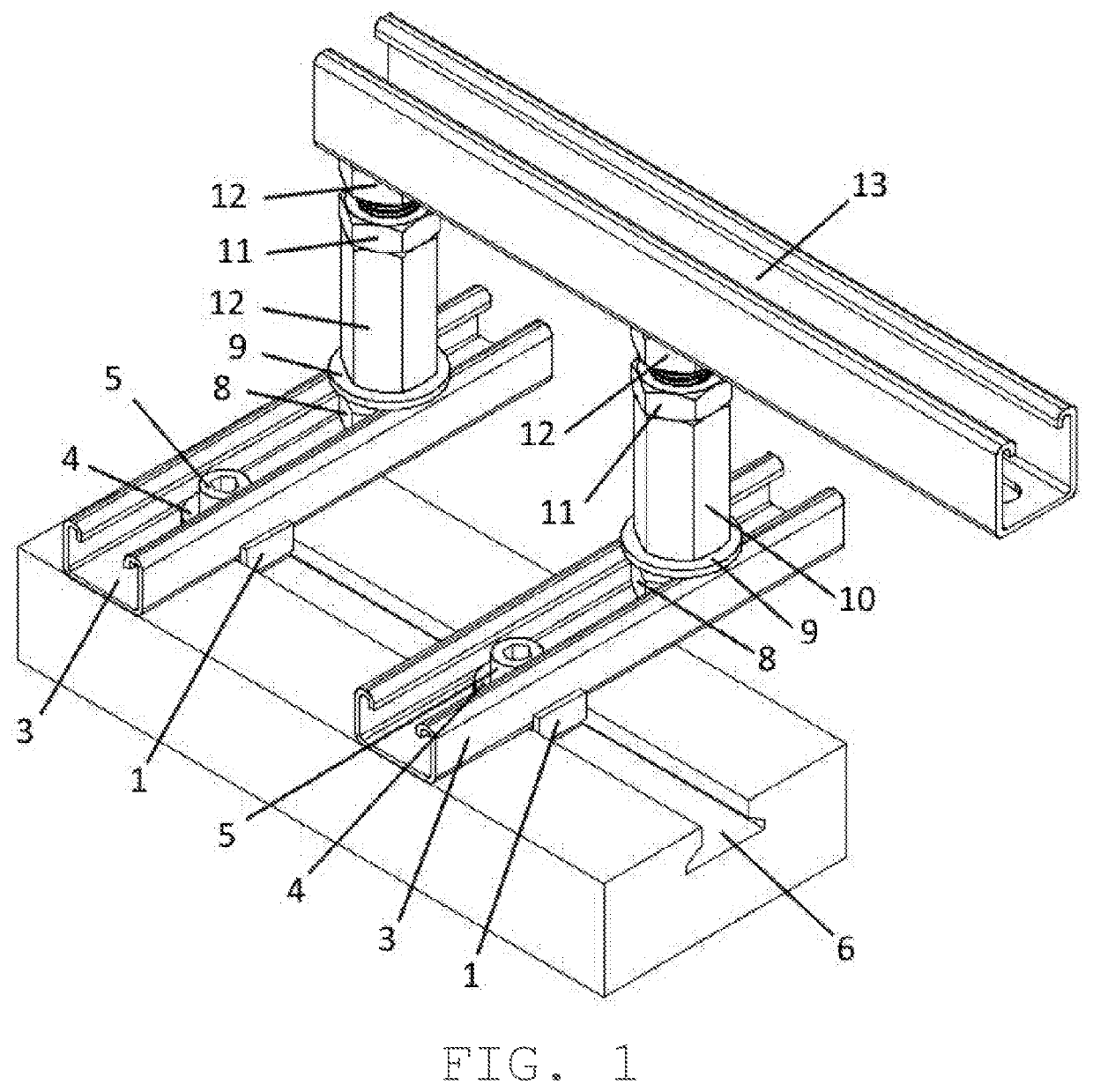
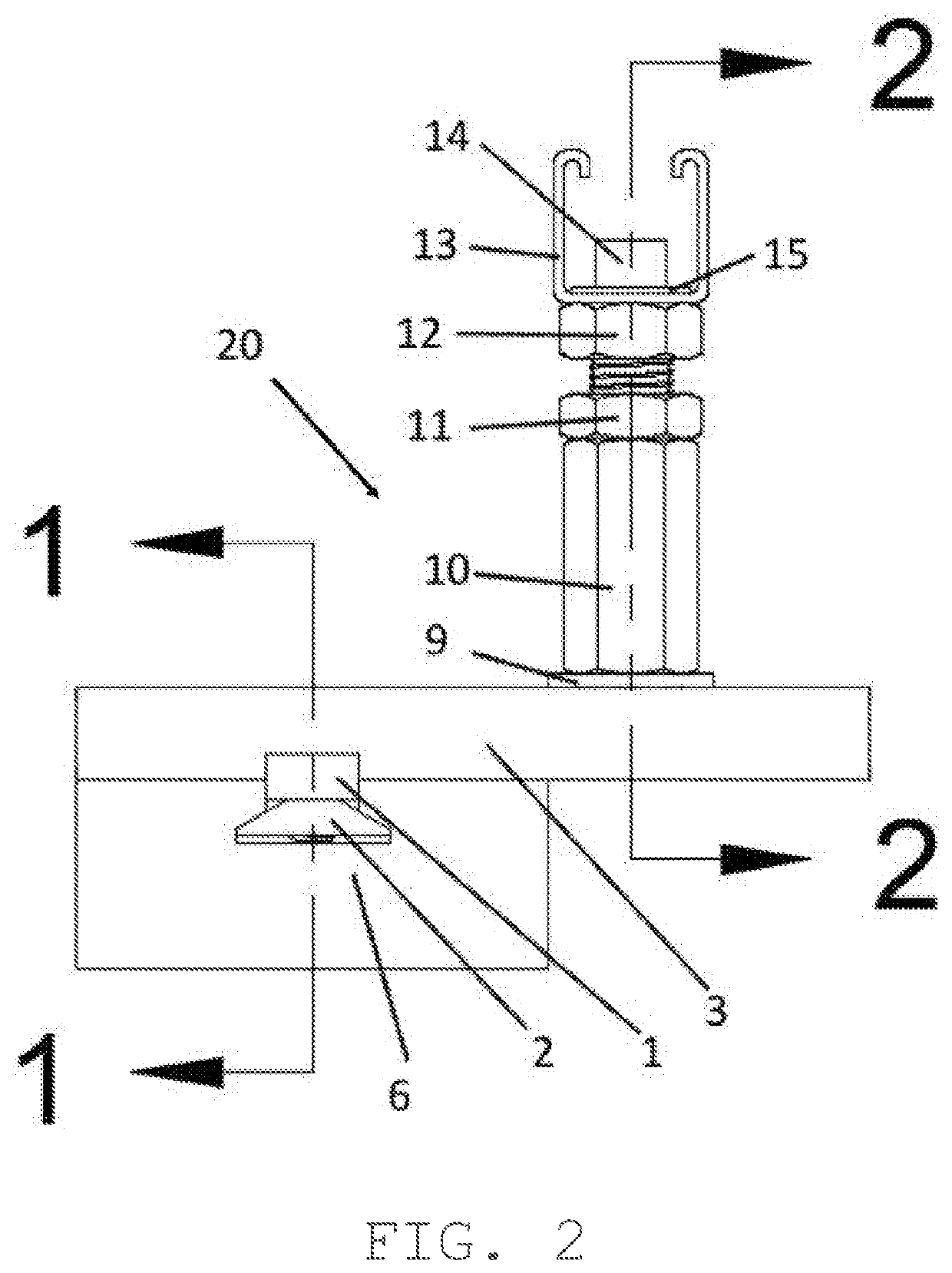
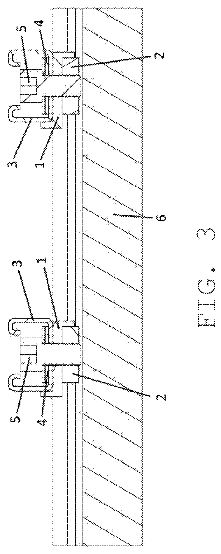
[0019]FIGS. 1 through 5 illustrate an EZ Speedy Fence Mount 20. The preferred embodiment of the present invention consists of two EZ Speedy Fence Mounts 20 and a track 13 to be used for linear measuring or gauging purposes. Depending on the application, fewer or more can be used to achieve the desired result. The EZ Speedy Fence Mount 20 consists of an engagement nut 2, held in the correct position by the opposing tooth key type aligner 1, that engages with the open-ended track 6. The opposing tooth key type aligner 1 is held in position by the track 3. A securing bolt 5 and a washer 4 provide a clamping force with the engagement nut 2 to secure the desired position in the open-ended track 6. Track 3 extends perpendicularly from the open-ended track 6. This creates a second axis of positional adjustment. Track 3 provides a means for which an anchor bolt 8 can slide into to allow for a washer 9 and coupler nut 10 to be placed on the anchor bolt 8 and rest on track 3. The coupler nut ...


PUM


Abstract

The invention allows for alignment perpendicular to a track engaged by a securing nut. An opposing tooth key type aligner has two functions: keeps the second track perpendicular to the first track and allows the securing nut to always be correctly oriented to engage with the track. A bolt clamps the securing nut to the track to lock the position of the invention. A second axis perpendicular to the lower track is created with a second track. A bolt connected to a coupler nut engages with the middle track to create a third axis perpendicular to both previous axes. A washer provides a neutral bearing surface between the coupler nut and second track. An elevation bolt sets the vertical position of the object to be mounted. A bolt can be used to fasten an object to the end of the elevation bolt.

Description

FIELD OF THE INVENTION[0001]The present invention relates generally to securing fences to machinery for the purposes of linear measuring and gauging, and more specifically, it relates to positioning a fence in all three axes of translation to acquire a precise surface for linear measuring and gauging of a work piece.DESCRIPTION OF THE PRIOR ART[0002]There is prior art of a mounting device made for an open track miter saw stand. It is a positioning mount that allows for vertical and horizontal positioning in relation to a fixed track. To use said mounting device, the user would need to remove the original work support that comes with the stand. They would then slide two of said prior art mounts into the open track and attach a work surface to the top of the mounts.[0003]The main problem with said prior art is the time and difficulty required to set the system up. The system consists of multiple components which must be placed individually into the track after removing an original com...

Claims


Application Information

Patent Timeline
Patent Type & Authority Applications(United States)
IPC IPC(8): B23Q3/00B23Q1/28
CPCB23Q1/28B23Q3/007B27B27/00B25H1/08B25H1/14
Inventor SUHLING, ROBERT JAMES
Owner SUHLING ROBERT JAMES
Why Eureka
Try Eureka