
Afterburner device and method for operating an afterburner device

a technology of afterburner and afterburner, which is applied in the direction of combustion types, lighting and heating apparatus, furnaces, etc., can solve the problems of large number of cold start phases, chemical reformer not working optimally, etc., to achieve good heat conductive contact, high degree of open porosity, and speed of reaction speed

Inactive Publication Date: 2010-07-27
ROBERT BOSCH GMBH
View PDF21 Cites 2 Cited by
  • Summary
  • Abstract
  • Description
  • Claims
  • Application Information

AI Technical Summary

Benefits of technology

The present invention provides a method and device for efficient and low-pollutant fuel distribution in an afterburner device. The method and device allow for good fuel distribution in the combustion chamber and foamed ceramics without the need for expensive atomization devices. The foamed ceramics heat up quickly, allowing for a brief cold start phase and a reduction in pollutant emissions. The recirculation of exhaust gases and heat exchange channels help to regulate the recirculated quantity of heat and improve fuel conversion. The foamed ceramics also store a certain quantity of fuel, which is available for combustion even after a brief interruption of the fuel supply. The afterburner device has a large heat output range and is adaptable to different load changing procedures. The combustion speed is determined by temperature measurement, and the quantity of recirculated combustion gases is regulated based on the determined combustion speed. The foamed ceramics are made at least partially of silicon carbide, which is heat resistant, conductive, and a good electrical conductor. The method and device allow for efficient and low-pollutant fuel distribution in an afterburner device.

Problems solved by technology

Particularly in vehicles for personal transportation, this leads to problems.
The numerous standstill phases of the vehicle lead to a large number of cold start phases, in which especially the chemical reformer does not function optimally.
At very slight load, the reformer also does not, under certain circumstances, achieve the optimal operating temperature by the heat arising in it, or loses it during the operation.
However, the heat energy of the combustible residual gases is generally not, by itself, sufficient for making available a sufficiently great heat output.
In this context, it may be a disadvantage that metering devices for generating a cloud of droplets having a small droplet diameter are very costly, cost intensive and subject to error.
The required small droplet diameter is often able to be achieved only by using high fuel pressure, the generation of high pressure requiring a relatively high quantity of power, and in particular, the equipment for generating the pressure requiring much space.
In addition, such metering devices usually have very small metering apertures, which, by combustion residues or deposits, change the metering behavior of the metering device in an impermissible and poorly controllable way.
In this connection, the disadvantages are the large space requirement, the control of the air metering that is costly and subject to interference, and the additional energy requirement.
Finally, especially at low power, the danger arises of unexpected extinguishing of the open continually burning flame in the combustion chamber.
Furthermore, there is always required a certain amount of time for shutting off the fuel supply or reigniting the flame.
This negatively influences the reignition, a catalytic converter that may possibly be present may be damaged, and uncombusted fuel and residual gas may escape into the atmosphere.
In spite of all the measures named, uncombusted or incompletely combusted portions remain behind in the exhaust gas of the afterburner device, which are, in part, poisonous or chemically aggressive.
This leads to increased environmental loading and material loading, and besides all that, the caloric value of the fuel or the residual gas is utilized only incompletely.

Method used


Image

  • Afterburner device and method for operating an afterburner device
  • Afterburner device and method for operating an afterburner device
  • Afterburner device and method for operating an afterburner device

Examples


Embodiment Construction

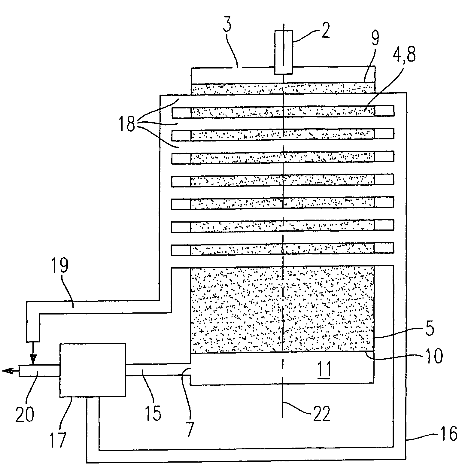
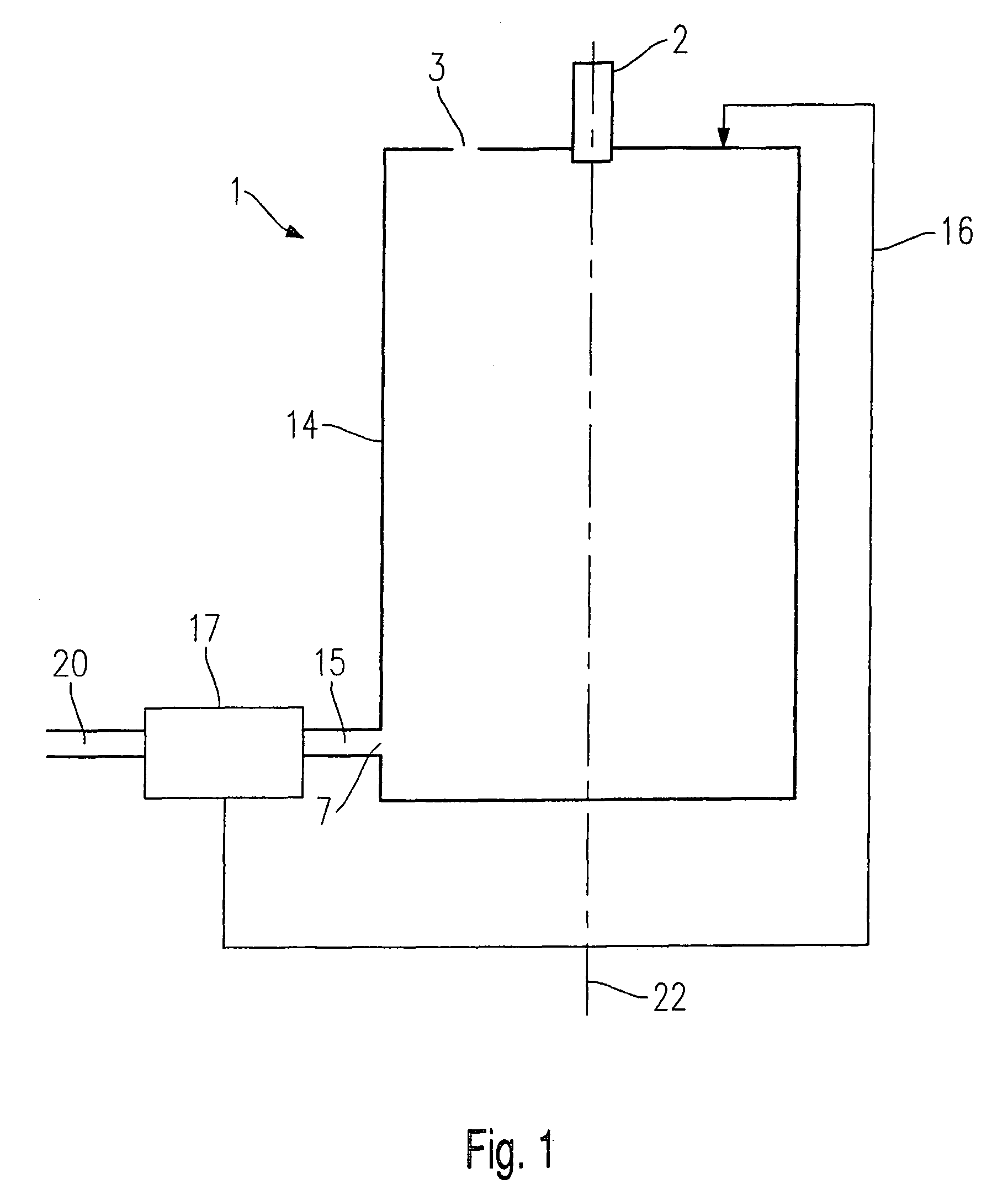
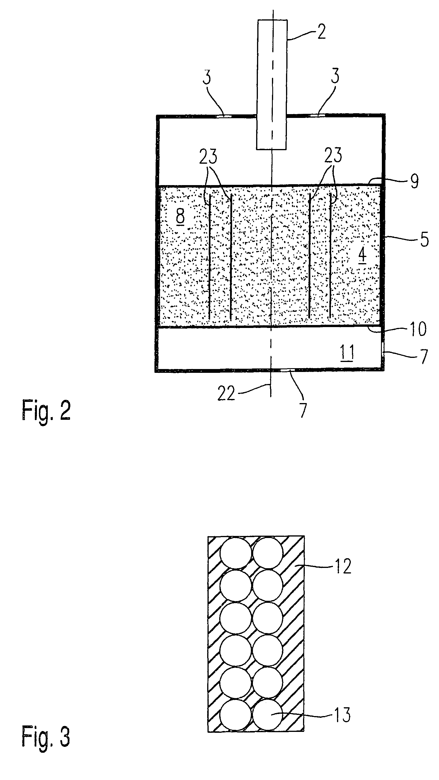
[0033]In the following, exemplary embodiments of the present invention are described by way of example. The example method according to the present invention is particularly advantageously used on these exemplary embodiments. Identical parts are provided with the same reference numerals in all the figures. The arrows represent the respective fuel and gas flows.

[0034]FIG. 1 shows an exemplary embodiment of an afterburner device 1 according to the present invention. The afterburner device has a cylindrical tubular second housing 14 closed at the ends, a nozzle 2, a controller 17 and a recirculating line 16. Nozzle 2 penetrates into the top end face of second housing 14, and is positioned axially centrically to an axis 22, which in this exemplary embodiment is identical to the axis of symmetry of second housing 14. The top end face of second housing 14 also has an air supply 3 which, in this exemplary embodiment, is implemented as just an opening. At the side, close to the lower end of...


PUM

PropertyMeasurementUnit
pore sizeaaaaaaaaaa
speedaaaaaaaaaa
speed of combustionaaaaaaaaaa

Abstract

An afterburner device and a method for operating an afterburner device, especially for chemical reformers for obtaining hydrogen, for making heat available from fuels and / or residual gases from a reforming process and / or a fuel cell process. In this context, heat is supplied in a controlled manner from recirculated combustion gases to a first housing and / or a combustion chamber situated in it and at least in part filled with heat resistant, open-pored foamed ceramics. The regulation takes place, for instance, based on a temperature recorded in the combustion chamber using an infrared light measurement.

Description

FIELD OF THE INVENTION[0001]The present invention relates to an afterburner device, and to a method for operating an afterburner device.BACKGROUND INFORMATION[0002]In fuel cell-supported transportation systems so-called chemical reformers are used for obtaining the required hydrogen from hydrocarbon-containing fuels.[0003]The optimal operating temperature of a chemical reformer is usually far above its surrounding temperature. Particularly in vehicles for personal transportation, this leads to problems. The numerous standstill phases of the vehicle lead to a large number of cold start phases, in which especially the chemical reformer does not function optimally. At very slight load, the reformer also does not, under certain circumstances, achieve the optimal operating temperature by the heat arising in it, or loses it during the operation.[0004]Therefore, particularly in the case of fuel cell supported drive systems having a chemical reformer, it may be of advantage to install after...

Claims


Application Information

Patent Timeline
Patent Type & Authority Patents(United States)
IPC IPC(8): F23C9/00B01J35/00H01M8/04H01M8/06
CPCH01M8/04014H01M8/0625Y02E60/50
Inventor HOENIG, GUENTERMILLER, FRANK
Owner ROBERT BOSCH GMBH
Learn More