
Recycling of oil-based drilling muds

a technology of oil-based drilling mud and oil-based mud, which is applied in the direction of dewatering/demulsification with chemical means, separation processes, and borehole/well accessories, etc., can solve the problems of complex and variable properties of drilling mud formulations, high cost, and high cost of formulation

Inactive Publication Date: 2010-07-13
LUBRIZOL OILFIELD SOLUTIONS
View PDF10 Cites 7 Cited by
  • Summary
  • Abstract
  • Description
  • Claims
  • Application Information

AI Technical Summary

Benefits of technology

This method achieves efficient separation and recycling of hydrocarbon base oils with high purity and recovery rates, reducing drilling costs and environmental impact by effectively removing ultra-fine and colloidal particles, and enabling the reuse of drilling fluids without the need for excessive dilution or environmentally harmful additives.

Problems solved by technology

Such fluids or mud formulations are typically tailored to specific well bore conditions and are costly to formulate.
The most expensive component of oil-mud systems is the hydrocarbon or synthetic base oil used as the fluid matrix for such systems.
The properties and composition of the drilling mud formulations are complex and variable, depending on the conditions involved and the results desired or required including the ability to reuse and recycle the mud formulations.
If mud solids are not properly controlled, the mud's density can increase above its desired weight and the mud can get so viscous that it creates difficulties in pumping the fluid.
The increase in density can become critical if the density exceeds the pore pressure of the formation which can lead to loss of the fluid and increased costs related thereto.
However, some drilled solids are so finely ground that they tend to remain in suspension regardless how long they are allowed to settle.
The fine solids in suspension result in increased mud viscosity and gel strength, which in turn results in larger particles also remaining in suspension.
Thus, the approach of removing cuttings through settling alone is of limited practical value.
These small particles, if not removed, create havoc in a variety of ways.
They slow the rate of penetration (ROP) compounding the number of rig days required and the cost.
They disrupt the drilling fluid rheology, especially gel strengths, thereby upsetting the Equivalent Circulating Density (ECD), risking mud losses and worse, creating potential blow out situations.
Ultra fine particles and colloidal particles cannot typically be removed by shale shakers, de-sanders, de-silters, or mud cleaners.
Under conventional methodologies, ultra fine particles and colloidal particles create the need for excessive dilution to control the fluid density thus escalating mud cost and worse, contributing to environmental disposal problems by excessive mud build-up.
As the solids surface area grows, water demand and chemical demand of the fluid grows, exponentially increasing demand for hydraulic horsepower, driving up plastic viscosity and creating sticky, spongy cakes on the wellbore walls.
Additional aqueous fluids that can be introduced into these systems can lead to significant difficulty in the recovery of the base oil fluid.
During the drilling process, it is also not uncommon for the drilling fluid to encounter a water bearing formation and thus, the ratio of aqueous fluid to non-aqueous fluid is less than optimal.
One of the primary difficulties associated with this system is the use of emulsion breakers and surface tension breakers that are not environmentally friendly.
There are a number of different methodologies noted in the literature for cleaning of drill solids, but very little has been done to address the recovery and reuse of the hydrocarbon base oil from an economic standpoint, which may lead to reduced oil and gas exploration costs.

Method used


Image

  • Recycling of oil-based drilling muds
  • Recycling of oil-based drilling muds
  • Recycling of oil-based drilling muds

Examples


example 1

[0052]The effectiveness of neutralization of the emulsifiers was tested using an embodiment of the invention to water wet the solids and remove the solids from the oil phase. Following treatment with an embodiment of the invention, a portion of the treated sample was centrifuged to remove the solids and a variety of individual tests were performed. As shown in Table 1, 11 samples are shown. Samples 10 and 11 are included to show that increasing acid volume did not further affect the density of the recovered oil.

[0053]Each 250 mL sample of solids-containing drilling fluid was added to a beaker and placed on to a paddle mixer at 200 rpm.

[0054]The properties of the drilling fluid samples prior to testing were as follows:[0055]1. Density: 1000 kg / m3 [0056]2. Oil / Water Ratio (OWR): 90 / 10[0057]3. Drilled Solids Concentration: 6% v / v[0058]4. Plastic Viscosity: 18 m.Pa.s[0059]5. Yield Point: 2.5 Pa[0060]6. Electrical Stability: 910

[0061]Sample 1 was not subjected to treatment according to e...

example 2

[0068]Samples of solids contaminated drilling fluid were treated according to embodiments of the invention using different v / v % DDBSA to illustrate that DDBSA, a known demulsifier and dispersant, acts as an exceptional surfactant to reduce the viscosity, especially the PV, as described herein and which aids in removing the solids. The same treatment method was used as in Example 1 and the results are shown below in Table 2.

[0069]

TABLE 2%Mix% v / vConcn% v / v% v / v#TimeHClHClNE005DDBSAPVYPESρoil10————151.59000.950216402000485.51700.925316402010474.51500.920440202011173400.855516402012192.5550.859

[0070]One skilled in the art can see in samples 4 and 5, that DDBSA aids in dispersing the organoclay and drilled solids as shown by the lower plastic viscosity (PV) and also aids in reducing the emulsion strength as shown by the lower electrical stability (ES).

[0071]The resulting recovered base oil has a lower density, approaching an ideal density, being that of the virgin base oil used in a dr...

example 3

[0072]Testing was conducted to illustrate the effect of different mixing times. The same test procedure was used as in Example 1 however the drilling fluid samples were obtained from a different wellbore. The drilling fluid had the following properties:[0073]1. Density: 1100 kg / m3 [0074]2. Oil / Water Ratio (OWR): 91 / 9[0075]3. Drilled Solids Concentration: 7% v / v[0076]4. Plastic Viscosity: 22 m.Pa.s[0077]5. Yield Point: 4.5 Pa[0078]6. Electrical Stability: 1260

[0079]

TABLE 3%Mix% v / vConcn% v / v% v / v#TimeHClHClNE005DDBSAPVYPESρoil1240251147131050.8652440200042111050.867364020103891000.865416 2020113371000.8655—————224.512600.920

[0080]It was noted that the electrical stability was higher than in the drilling fluid used in Example 1 which is an indication that there was more emulsifier present in the drilling fluid used in this example. A higher concentration of acid was therefore required for neutralization of the increased amount of emulsifier.

[0081]One skilled in the art can see that mi...


PUM

PropertyMeasurementUnit
volume %aaaaaaaaaa
volume %aaaaaaaaaa
sizeaaaaaaaaaa

Abstract

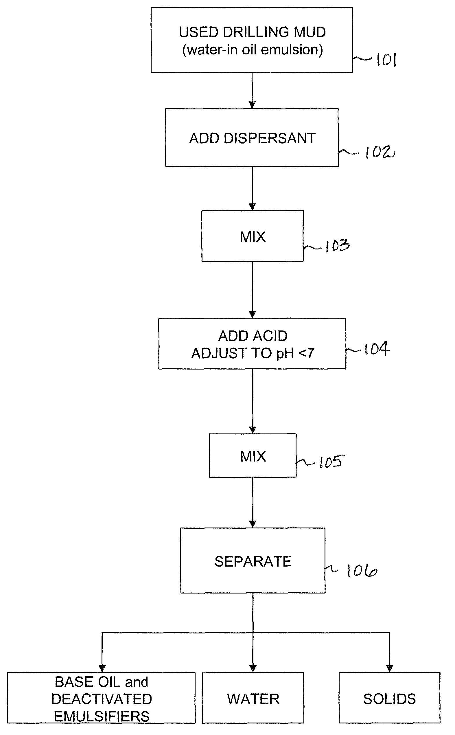
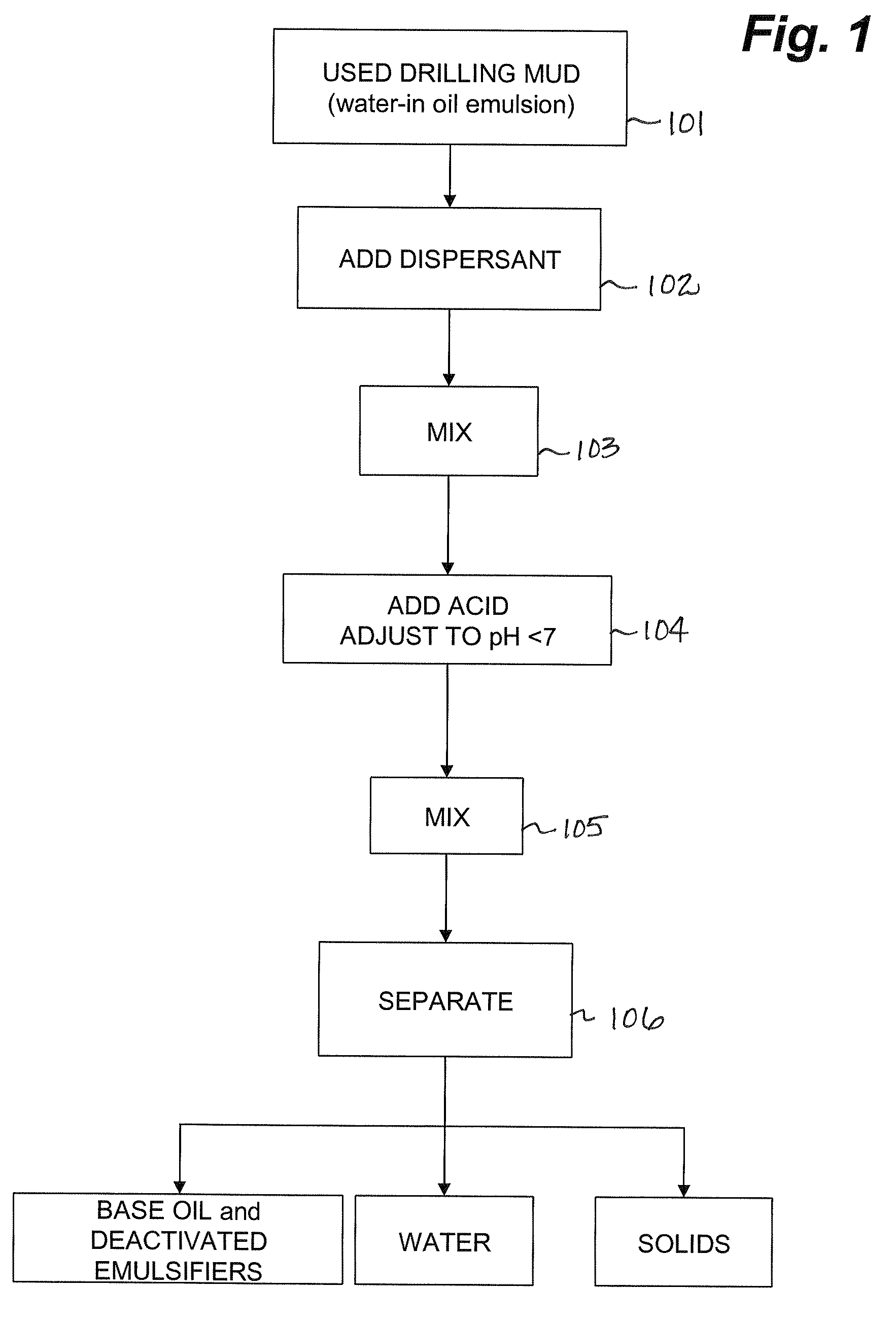
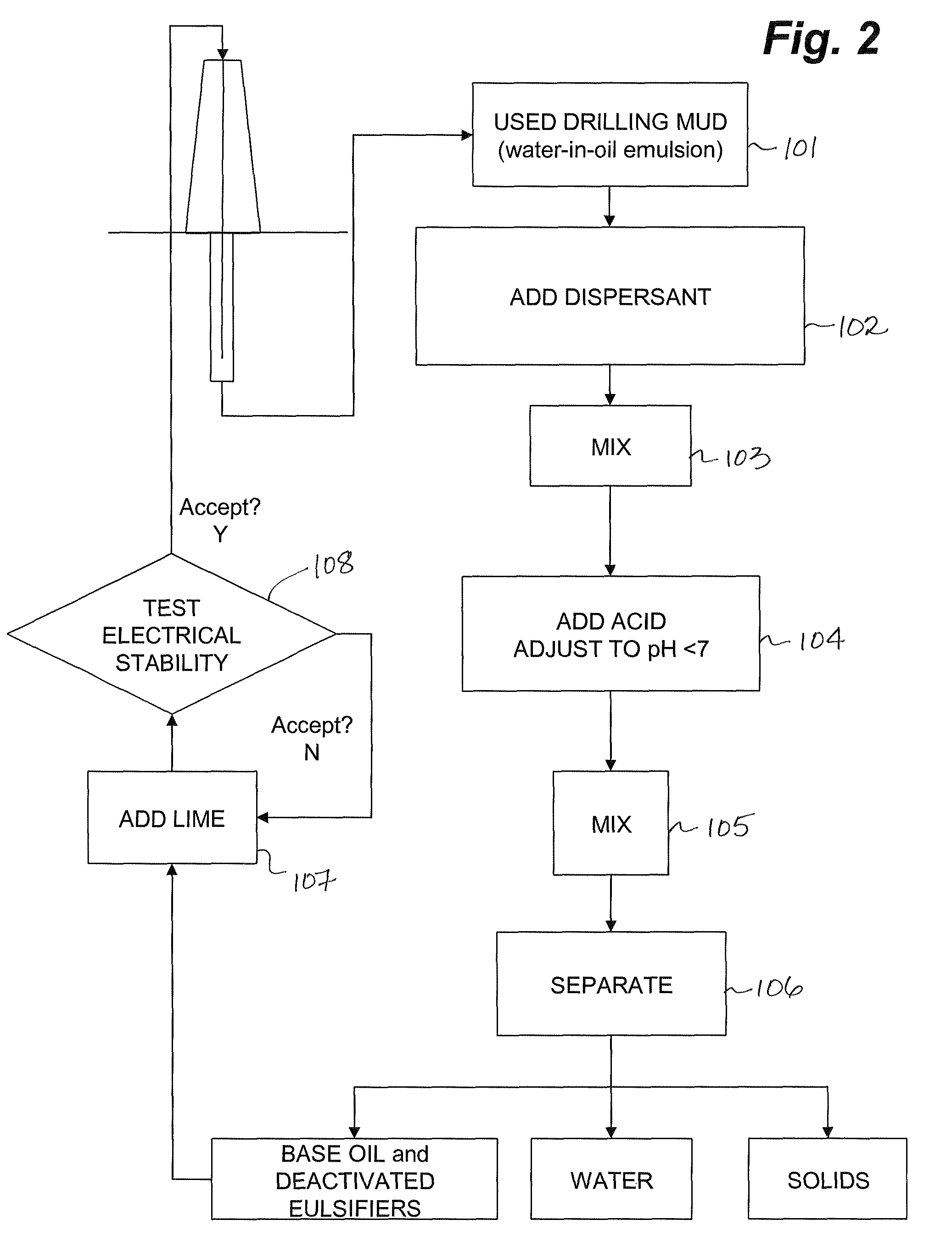
A method of recovering hydrocarbon or synthetic base oils from used oil-based drilling mud utilizes acid to deactivate emulsifiers in the drilling mud for altering the emulsion stability and permitting removal of the solids contained in the drilling mud using conventional separation such as centrifugation. A surfactant is typically added to prevent water-wetting as a result of the addition of the acid. The recovered base oil contains substantially all of the deactivated emulsifiers, which can be reactivated through the addition of lime, allowing new drilling fluids to be prepared without the need to add significant amounts of emulsifier to the recycled base oil.

Description

CROSS REFERENCE TO RELATED APPLICATION[0001]This application is a regular application claiming priority of U.S. Provisional Patent application Ser. No. 60 / 867,420, filed on Nov. 28, 2006, the entirety of which is incorporated herein by reference.FIELD OF THE INVENTION[0002]Embodiments of the invention relate to processes for recycling hydrocarbon and synthetic base oils from drilling fluids and more particularly to processes of removing ultra-fine particulate materials for recycling the base oil for use in preparing drilling fluids without the need to add additional emulsifiers.BACKGROUND OF THE INVENTION[0003]Water-in-oil emulsions (oil-mud) are often used in circulating fluids required in the rotary drilling of formations containing hydrocarbons. The circulating fluids are referred to as drilling muds. The common specification of the term “mud” is defined according to its usual meaning in the oil and gas drilling industries, namely to describe a drilling fluid used to transport ro...

Claims


Application Information

Patent Timeline
Patent Type & Authority Patents(United States)
IPC IPC(8): C10G17/02C10M175/04C09K8/36C10G19/073
CPCB01D17/047C10G1/00C10G33/04E21B21/06E21B21/068B01D17/0217
Inventor SMITH, CLAYTONLEVEY, SIMON JOHN MICHAEL
Owner LUBRIZOL OILFIELD SOLUTIONS
Learn More