Ceramic optical parts and production methods thereof

a technology of ceramic optical parts and production methods, which is applied in the direction of ceramicware, domestic applications, other domestic objects, etc., can solve the problems of high uniformity and high accuracy, increase the cost, and achieve high uniformity, high accuracy, and small reflection

Active Publication Date: 2010-07-06
FUJIFILM CORP +1
View PDF19 Cites 0 Cited by
  • Summary
  • Abstract
  • Description
  • Claims
  • Application Information

AI Technical Summary

Benefits of technology

[0006]Under such a situation and by taking the aforementioned prior arts into consideration, the present inventors have carried out intensive studies with the aim of developing a ceramic material for an optical member use and product thereof which can be suitably used as a highly uniform and highly accurate optical part by its sintering alone without carrying out a secondary processing, and have succeeded as a result in developing a novel ceramic material that can be used as an optical part, making use of a ceramic porous body which is a reaction-sintered sintered ceramic body prepared by synthesizing it making use of a reaction sintering and has a predetermined porosity, thus resulting in the accomplishment of the invention. The invention aims at providing a novel ceramic material which can be suitably used as a highly accurate and highly uniform optical part by its sintering alone. In addition, another purpose of the invention is to provide a novel ceramic optical part in which entire or a portion of the part is constructed with a novel porous ceramic that can be sufficiently used as an optical part having small reflection at visible light region and high accuracy, making use of said ceramic material.

Problems solved by technology

However, in the case of compact ceramics, accuracy of the sintered body varies due to large shrinkage at the time of sintering, which results in the necessity to carry out a secondary processing and thereby poses a problem of increased cost or the like when, for example, this is used as an optical part for which high uniformity and high accuracy are required.

Method used


Image

  • Ceramic optical parts and production methods thereof
  • Ceramic optical parts and production methods thereof
  • Ceramic optical parts and production methods thereof

Examples


##ventive example 1

Inventive Example 1

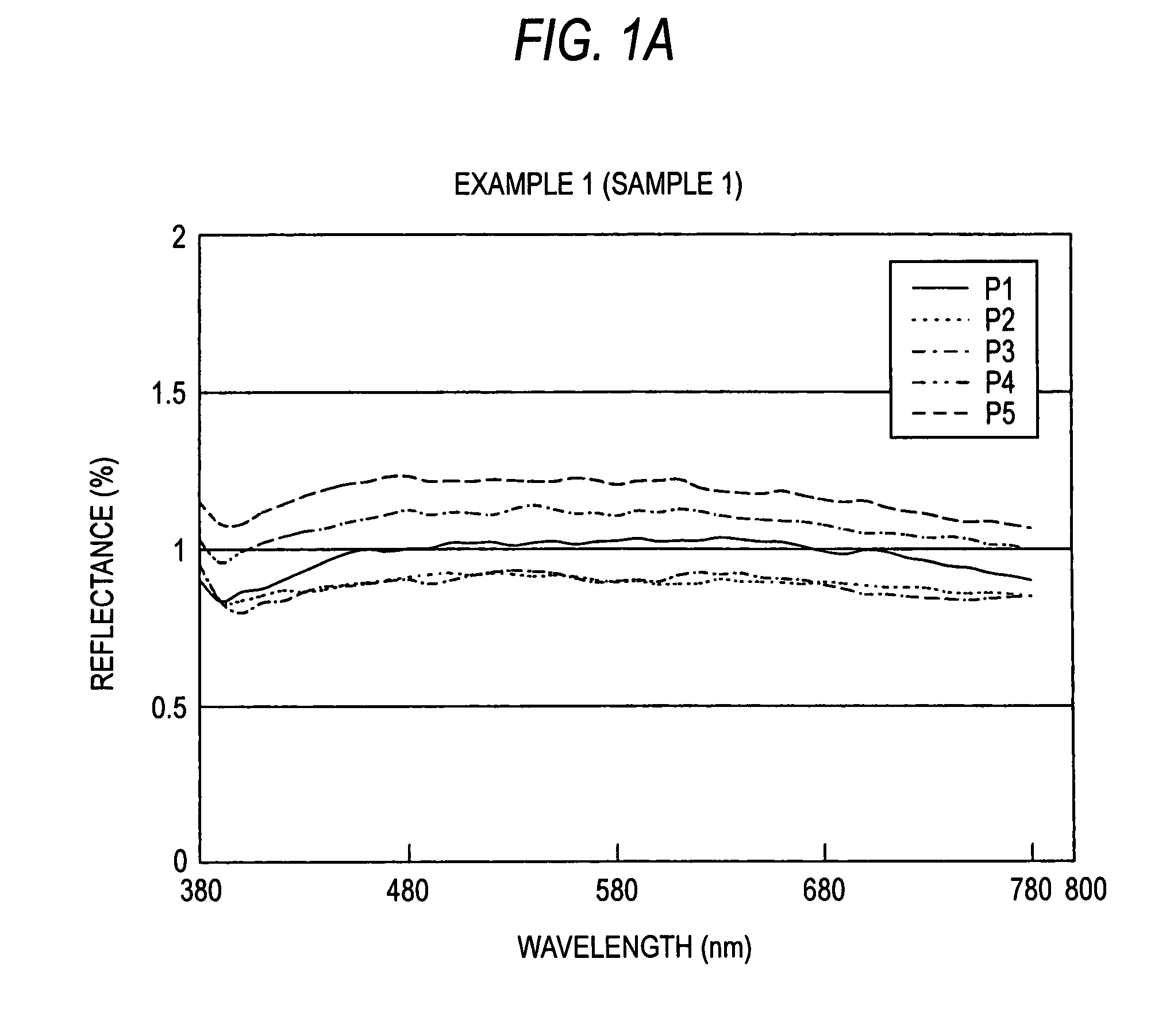
[0037]Blending weight ratios of the used raw material powders (compositions of mixed powders) are shown in Table 1. As the component which accelerates blackening, 15 wt % Fe2O3 was added to silicon powder. In the same manner, WB, B4C, MoO3, Fe3O4, Ta2O5, ZrO2 or Cr2O3 was added at the aforementioned ratio. Each of these raw materials was weighed, mixed with 1.5 times in total powder weight of distilled water and a polyvinyl alcohol aqueous solution, mixed using a ball mill for about 6 hours to make a slurry and then subjected to spray drying to prepare granulated powder. Next, the granulated powder was put into a die of 20×80 mm in inner dimension, preformed under a pressure of 8.3 MPa, put into a nylon bag and then sealed therein by reducing the inside pressure.

[0038]

TABLE 1Sample No.SiFe2O3WBB4CMoO3Fe3O4Ta2O5ZrO2Cr2O31851528515385154851558515685157851588515

[0039]This was pressurized using CIP under a pressure of 200 MPa to obtain a formed body. Subsequently, thi...

##ventive example 2

Inventive Example 2

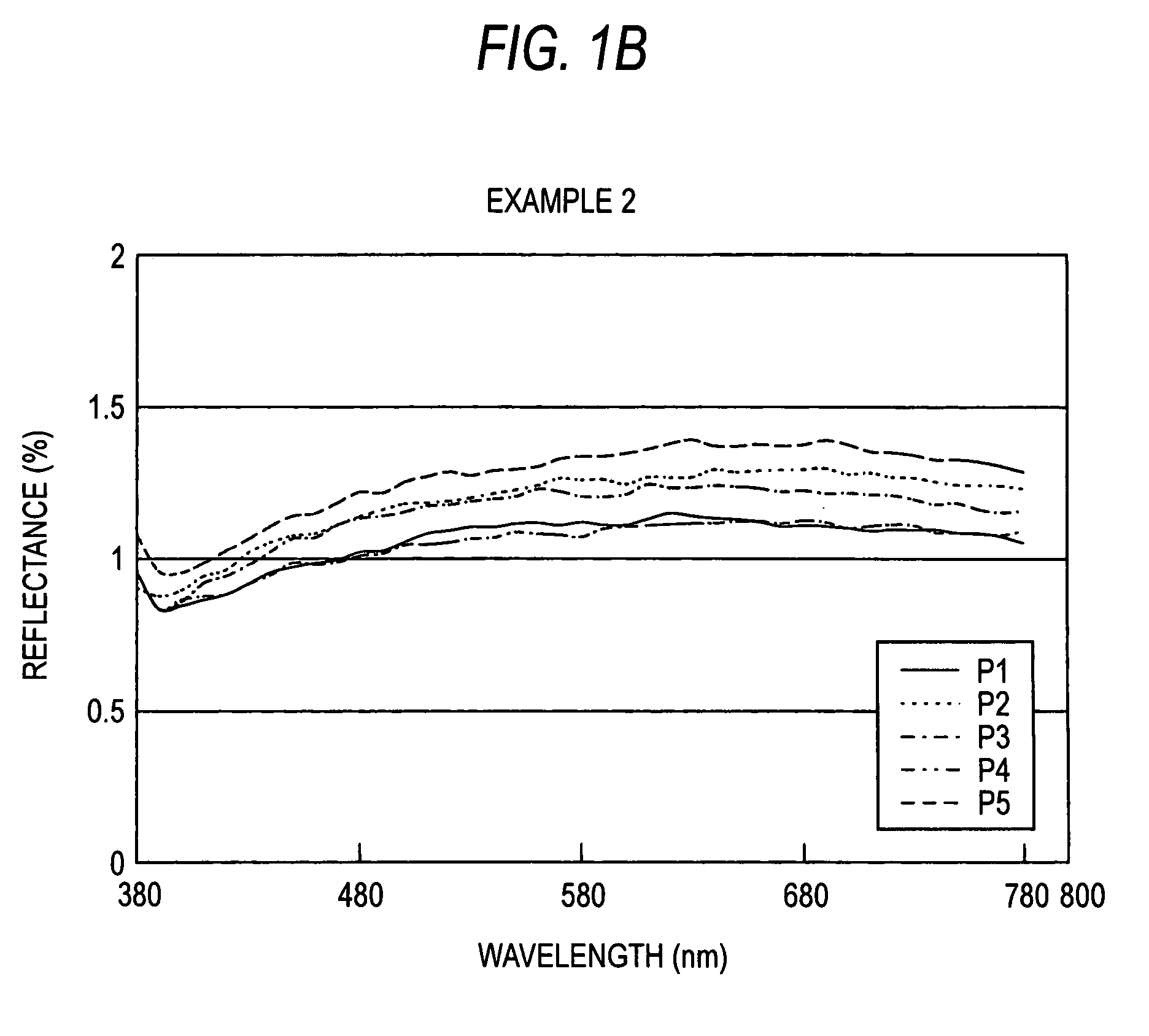
[0040]Silicon carbide and carbon were weighed at a weight ratio of 6:4, and 15% Fe2O3 was added thereto. These weighed powders were mixed with 1.5 times in total powder weight of alcohol and a polyvinylbutyral alcohol solution, mixed using a ball until for about 6 hours to make a slurry and then subjected to spray drying to prepare granulated powder. Next, the granulated powder was put into a die of 20×80 mm in inner dimension, preformed under a pressure of 8.3 MPa, put into a nylon bag and then sealed therein by reducing the inside pressure.

[0041]This was pressurized using CIP under a pressure of 200 MPa to obtain a formed body. Subsequently, the thus obtained formed body was put into a crucible of boron nitride spread with silicon, and then heated to 1,500° C. in an atmosphere of Ar under 0.1 MPa to carry out its reaction sintering. After the reaction sintering measurement of reflectance on the sample surface at the visible light region was carried out. Namely, ...

##ventive example 3

Inventive Example 3

[0042]As the components which accelerate blackening, 2% MoO3, 2% Fe2O3 and 2% Cr2O3 were added to respective raw materials alumina and zirconia, and these raw materials were weighed, mixed with 1.5 times in total powder weight of distilled water and a polyvinylalcohol aqueous solution, mixed using a ball mill for about 6 hours to make a slurry and then subjected to spray drying to prepare granulated powder.

[0043]Next, the granulated powder was put into a die of 20×80 mm in inner dimension, preformed under a pressure of 8.3 MPa, put into a nylon bag and then sealed therein by reducing the inside pressure. This was pressurized using a CIP device under a pressure of 200 MPa to obtain a formed body. Subsequently, the thus obtained formed body was subjected to a degreasing treatment by heating it to 550° C. in an atmosphere of N2 under 0.2 MPa, and then to a reaction sintering at 1,250° C. for 1 hour in an atmosphere of N2 under 0.1 MPa. After the sintering, measuremen...


PUM

PropertyMeasurementUnit
porosityaaaaaaaaaa
reflectanceaaaaaaaaaa

Abstract

A ceramic material for an optical member which shows black, wherein the ceramic material comprises a reaction-sintered sintered ceramic body prepared by synthesizing a formed body of a mixture comprising a ceramic raw material and a component that accelerates blackening, making use of a reaction sintering; and wherein the ceramic material is a porous body.

Description

BACKGROUND OF THE INVENTION[0001]1. Field of the Invention[0002]This invention relates to a ceramic material for an octal member, a production method thereof and a ceramic optical part, more particularly to a black and porous ceramic material which can be used in an octal part, a ceramic optical part and production methods thereof. The invention provides a novel ceramic material for an optical member, which is a ceramic material for an optical member constituted from a porous reaction-sintered sintered ceramic body that shows black, wherein it shows no variation regarding the accuracy of the sintered body, its reflectance at the visible light region is 20% or less, its surface is an unprocessed baked face and it can be suitably used as a high accuracy and high quality optical part, and provides new techniques and new product regarding ceramic optical parts.[0003]2. Description of the Related Art[0004]In a preceding reference, examples are reported for example on the use of a ceramic...

Claims


Application Information

Patent Timeline
Patent Type & Authority Patents(United States)
IPC IPC(8): C04B35/563C04B35/584C04B35/599C04B35/582C04B35/565
CPCC04B35/119C04B35/4885C04B35/573C04B35/584C04B35/591C04B35/597C04B35/6342C04B35/638C04B35/65C04B2235/3217C04B2235/3225C04B2235/3241C04B2235/3251C04B2235/3272C04B2235/3826C04B2235/422C04B2235/604C04B2235/658C04B2235/9661
Inventor HYUGA, HIDEKIKITA, HIDEKIYAMAZAKI, TETSUYATANAKA, YASUNORI
Owner FUJIFILM CORP
Why Eureka
Try Eureka