Transmission circuit, and communication apparatus using the same
a transmission circuit and communication apparatus technology, applied in the field of transmission circuits, can solve the problems of difficult to output a desired transmission signal sb>0/b, difficult to output a highly linear transmission signal in such an area, and achieve the effect of high efficiency
- Summary
- Abstract
- Description
- Claims
- Application Information
AI Technical Summary
Benefits of technology
Problems solved by technology
Method used
Image
Examples
first embodiment
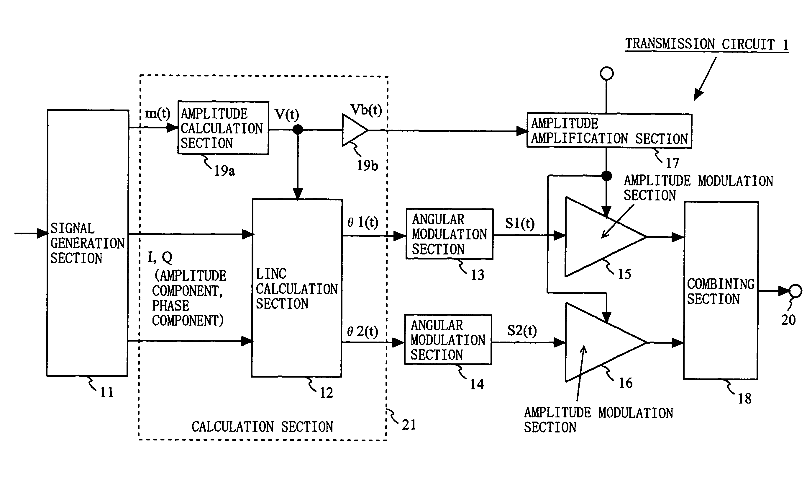
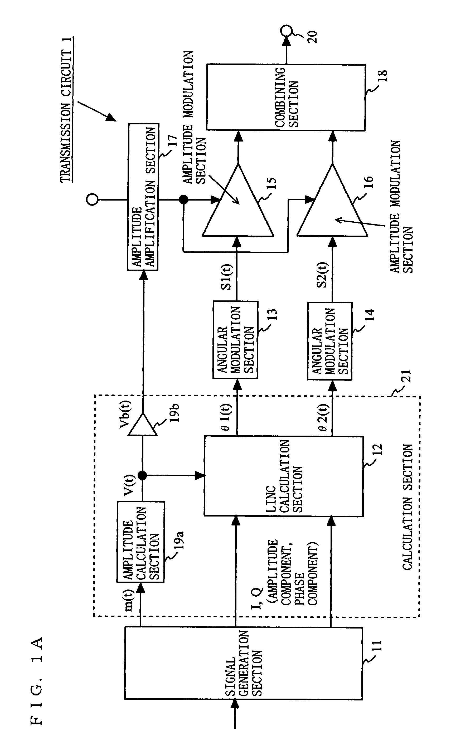
[0077]FIG. 1A is a block diagram showing an exemplary structure of a transmission circuit 1 according to a first embodiment of the present invention. As shown in FIG. 1A, the transmission circuit 1 includes a signal generation section 11, a LINC calculation section 12, an angular modulation section 13, an angular modulation section 14, an amplitude modulation section 15, an amplitude modulation section 16, an amplitude amplification section 17, a combining section 18, an amplitude calculation section 19a, an amplification section 19b, and an output terminal 20. The LINC calculation section 12, the amplitude calculation section 19a and the amplification section 19b may be represented as being included in a calculation section 21.
[0078]The signal generation section 11 modulates input data to generate signals of a predetermined form and an amplitude signal m(t). The signals of a predetermined form are I and Q signals, which are quadrature signals. The amplitude signal m(t) is represent...
second embodiment
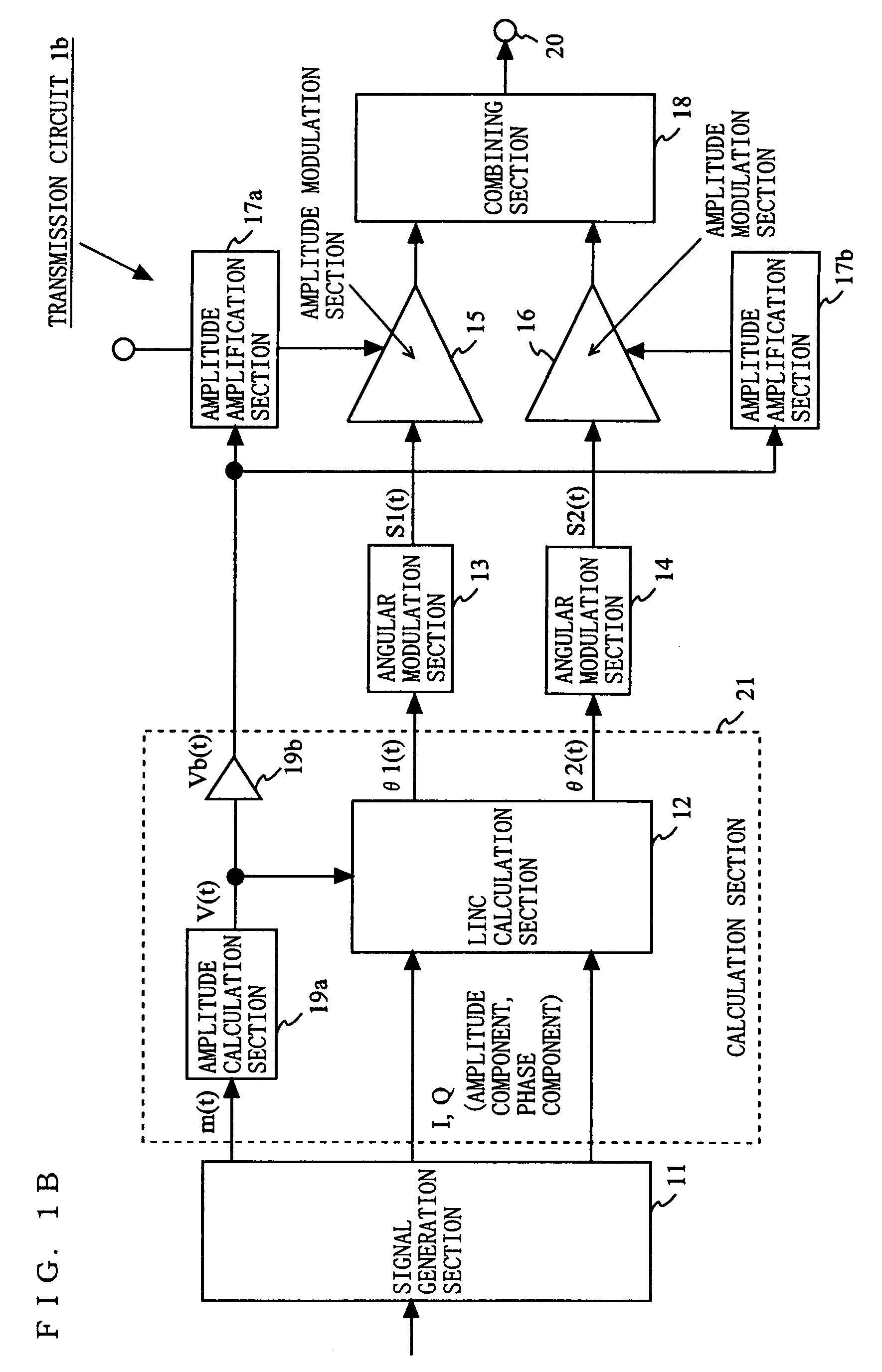
[0114]FIG. 9 is a block diagram showing an exemplary structure of a transmission circuit 2 according to a second embodiment of the present invention. As shown in FIG. 9, the transmission circuit 2 includes a timing control section 22 in addition to the elements included in the transmission circuit 1 according to the first embodiment. The amplitude amplification section 17 includes a series regulator 17a and a switching regulator 17b. The switching regulator 17b supplies a voltage to the series regulator 17a. The series regulator 17a supplies a voltage to the amplitude modulation sections 15 and 16. The series regulator 17a and the switching regulator 17b have the same structures as those shown in FIG. 7A and FIG. 7B.
[0115]FIG. 10 shows an exemplary timing diagram of the signals handled by the transmission circuit 2. With reference to FIG. 10, the transmission circuit 2 according to the second embodiment will be described. To the calculation section 21, an amplitude signal m(t) is in...
third embodiment
[0119]FIG. 11 is a block diagram showing an exemplary structure of a transmission circuit 3 according to a third embodiment of the present invention. As shown in FIG. 11, the transmission circuit 3 includes a variable gain amplification section 23 and a variable gain amplification section 24 instead of the amplitude amplification section 17 included in the transmission circuit 1 according to the first embodiment. To the variable gain amplification sections 23 and 24, a discrete value Vb(t) is input from the calculation section 21. The variable gain amplification section 23 amplifies the first angle-modulated signal S1(t) with a gain in accordance with the level of the discrete value Vb(t). The variable gain amplification section 24 amplifies the second angle-modulated signal S2(t) with a gain in accordance with the level of the discrete value Vb(t). The amplified first angle-modulated signal S1(t) and second angle-modulated signal S2(t) are respectively input to the amplitude modula...
PUM
 Abstract
Description
Claims
Application Information
 - R&D
- Intellectual Property
- Life Sciences
- Materials
- Tech Scout
- Unparalleled Data Quality
- Higher Quality Content
- 60% Fewer Hallucinations
Browse by: Latest US Patents, China's latest patents, Technical Efficacy Thesaurus, Application Domain, Technology Topic, Popular Technical Reports.
© 2025 PatSnap. All rights reserved.Legal|Privacy policy|Modern Slavery Act Transparency Statement|Sitemap|About US| Contact US: help@patsnap.com


