
Highly extensible power and/or signal transmission cable as well as rotor blade with such a cable

a technology of power and/or signal transmission and rotor blade, which is applied in the direction of insulated conductors, cables, vessel construction, etc., can solve the problems of rotor blades being severely deformed, wires or conductors of cables breaking or failing very quickly, and electric signal or power transmission cables having metal wires or conductors failing quite soon, so as to improve fatigue strength and long-term transmission properties

Inactive Publication Date: 2010-06-22
AIRBUS HELICOPTERS DEUT GMBH
View PDF7 Cites 4 Cited by
  • Summary
  • Abstract
  • Description
  • Claims
  • Application Information

AI Technical Summary

Benefits of technology

The present invention provides a cable design that improves the fatigue strength and long-term transmission properties of cables that are exposed to high mechanical or dynamic stress due to strains. The cable has a spiral-like structure with a predefined pitch angle and is wound around a first cable core made of an elastic plastic material. The cable wires are wound at a predefined angle and are free of crossovers, which prevents abrasion and failure. The cable design allows for durable and long-lasting energy and power transmission to and from functional devices in a rotor blade.

Problems solved by technology

Moreover, the rotor blades are severely deformed by alternating dynamic and aerodynamic forces during a rotation of the rotor blade.
If the rotor blade is equipped with power and signal transmission cables, it has been found that, under the described high dynamic loads, the wires or conductors of the cable very quickly break or fail.
Especially electric signal or power transmission cables having metal wires or conductors fail quite soon.
Consequently, sufficient fatigue strength of the cable can no longer be ensured.
The result of this, in turn, is that it is not possible to ensure reliable operation of the appertaining functional device that is being supplied with power by such a cable or that receives or emits signals via such a cable.
Moreover, if the cable fails, the appertaining rotor blade in which this cable is installed has to be replaced or repaired.
This, however, entails tremendous technical effort and costs.
However, it has been found that the shielding of these cables also fails too soon as a result of the above-mentioned high centrifugal forces so that reliable shielding cannot be ensured.
The installation of power and / or signal transmission cables in the rotor blade is also very complex.
Consequently, repeated installation of a cable in and dismantling of a cable from a fiber-composite rotor blade is extremely complex and is associated with a great deal of production and assembly work as well as considerable costs.

Method used


Image

  • Highly extensible power and/or signal transmission cable as well as rotor blade with such a cable
  • Highly extensible power and/or signal transmission cable as well as rotor blade with such a cable
  • Highly extensible power and/or signal transmission cable as well as rotor blade with such a cable

Examples


first embodiment

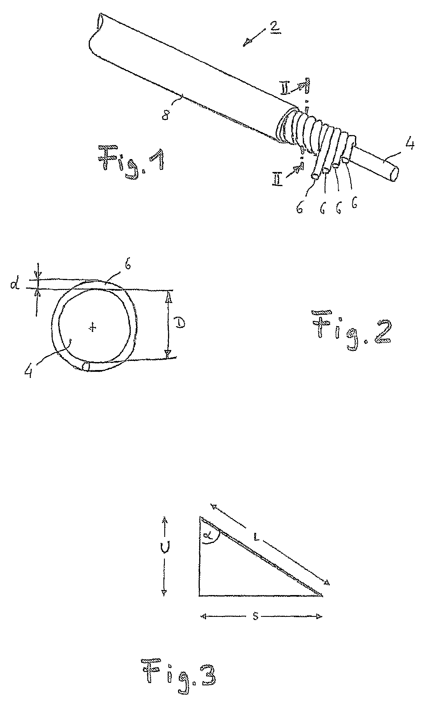
[0058]FIG. 1 shows a schematic perspective view of a highly extensible power transmission cable 2 (hereinafter referred to in short as cable 2) according to the invention in a FIG. 2 shows a schematic, enlarged sectional view through the cable 2 according to the invention along the line II-II in FIG. 1.

[0059]In this example, the cable 2 comprises a single cable strand with a first cable core 4 made of an electrically insulating, elastic plastic material and four first cable wires 6 that are wound loosely around the first cable core 4 at a predefined pitch angle, like a spiral and free of crossovers. The cable wires 6 are configured as electric conductors and are made of a copper material. The cable 2 has an outer, electrically insulating insulation layer 8 that sheathes the four first cable wires 6.

[0060]The first cable core 4 is made of polytetrafluoroethylene (PTFE). The modulus of elasticity is 420 N / mm2. The Shore hardness according to ISO 868 is D55. The Poisson ratio of the f...

second embodiment

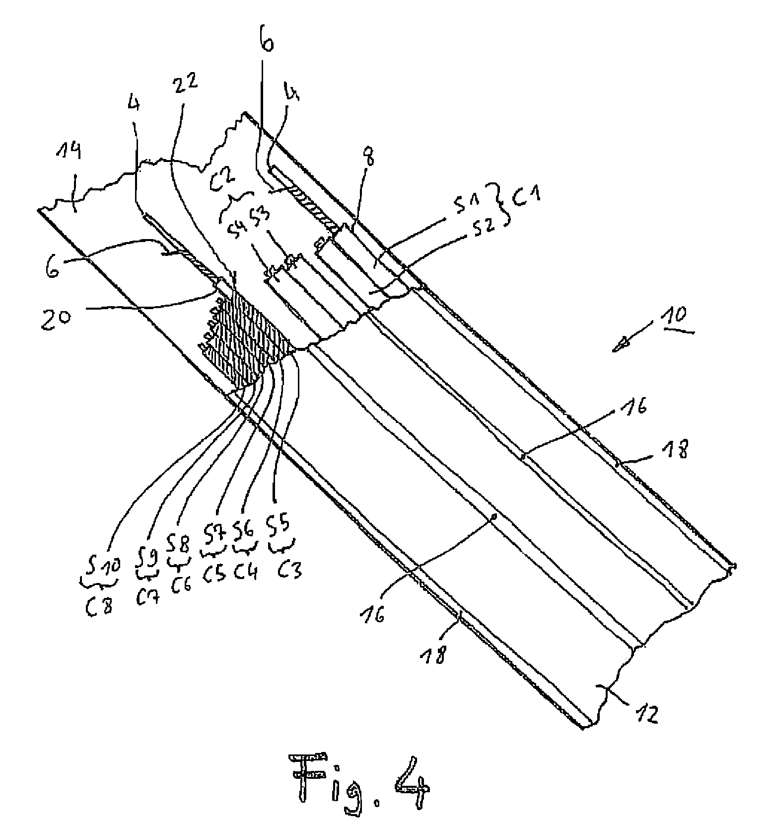
[0082]FIG. 4 shows a schematic top view of a cable 10 according to the invention in a This cable 10 in the form of a flat cable is a highly extensible power and / or signal transmission cable, which has several, that is to say, here ten, cable strands S1 to S10 lying next to each other.

[0083]These cable strands S1 to S10 are arranged parallel next to each other between two strip-shaped, film-like support layers 12, 14 made of a plastic material. The support layers 12, 14 have essentially the same extensibility and minimum temperature resistance as the previously described first cable core 4. The four cable strands S1 to S4 each form a two-pole electric power transmission line C1, C2. The remaining six cable strands are six signal transmission lines C3 to C8 each configured as a coaxial line. The two power transmission lines C1, C2 are separated from each other as well as from the signal transmission lines C3 to C8 by a separation area 16 at which the two support layers 12, 14 are joi...


PUM


Abstract

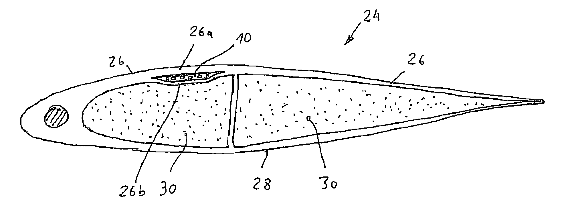
A fiber-composite rotor blade, especially of a rotary-wing aircraft, with a predefined rotor blade profile that has a predefined outer contour of the profile. The fiber-composite rotor blade includes a fiber-composite rotor blade structure having an upper and a lower cover skin and a profile core situated between them, and at least one highly extensible cable integrated into the fiber-composite rotor blade structure in the direction of the span of the rotor blade, whereby the cable can be connected to a functional device that can be attached onto or into the fiber-composite rotor blade structure. The cable is a highly extensible power and / or signal transmission cable that includes at least one cable strand with at least one first cable core made of an electrically insulating, elastic plastic material, and at least one first cable wire that is wound around the first cable core at a predefined pitch angle, like a spiral and free of crossovers.

Description

[0001]Priority is claimed to German Patent Application No. 10 2005 062 347.6, filed on Dec. 23, 2005, the entire disclosure of which is incorporated by reference herein.[0002]The present invention relates to a power and / or signal transmission cable as well as to a rotor blade, especially a rotor blade of a rotary-wing aircraft, having such a cable.BACKGROUND[0003]Rotor blades made of fiber-composite materials are used especially in rotors of modern rotary-wing aircraft such as, for example, helicopters, because of their special suitability for high, alternating dynamic and aerodynamic loads. In recent times, such rotor blades have been increasingly equipped with special functional devices that make it possible, for example, to systematically influence the aerodynamic and acoustic properties of a rotor. These functional devices can be, for example, actuators for an adjustable rotor blade flap arranged near the tip of the rotor blade, sensors installed on the rotor blade, a heating un...

Claims


Application Information

Patent Timeline
Patent Type & Authority Patents(United States)
IPC IPC(8): B63H1/26
CPCB64C27/473H01B7/065B64C2027/4736Y02E10/721H01B7/1825Y02E10/72
Inventor MUELLER, CHRISTINEPREISSLER, DIETER
Owner AIRBUS HELICOPTERS DEUT GMBH
Learn More