Screen assembly for a pulp digester

a technology of pulp digester and assembly, which is applied in the direction of moving filter element filter, separation process, filtration separation, etc., can solve the problems of affecting the operation of the digester, and involving a significant amount of work, so as to minimize the formation of cracks, improve the efficiency of the digester, and accommodate the pressure change within the vessel

Inactive Publication Date: 2010-06-15
METSO PAPER PORI OY
View PDF7 Cites 0 Cited by
  • Summary
  • Abstract
  • Description
  • Claims
  • Application Information

AI Technical Summary

Benefits of technology

[0016]Although the present invention is not limited by any particular theory of operation, it is believed that providing screen assemblies that are movable relative to the vessel wall will solve a number of problems associated with digesters. First, the movable screen assembly of the present invention can better accommodate pressure changes within the vessel because the screen assembly can move in response to high-pressure areas within the vessel. Thus, the movable screen of the present invention enables pressure to be more evenly distributed throughout the vessel. Second, the ability of the screen assemblies of the present invention to move tends to minimize the formation of cracks in either the screen assembly or the welds used to position the screen assembly within the vessel. This feature overcomes problems found in prior art digesters that use thousands of welds to hold screens in place. These welds tend to crack under pressure or during long-term use, which results in maintenance problems or downtime for the digester. Third, the movable screen assemblies of the present invention can be used in a wide variety of digesters having different inner wall surfaces. As is well known to those skilled in the art, no two digesters are the same. This often makes it difficult to weld prior art screens to the vessel wall. However, this problem of matching the contour of the screen to the contour of the vessel wall is solved with the present invention because the screen floats and / or is movable relative to the vessel wall, thereby minimizing the need for providing exacting tolerances between the contour of the screen assembly and the contour of the vessel wall. The present invention also enables digesters to be assembled in less time and at lower cost. This is due, in part, to the fact that fewer welds are required for positioning the screens within a vessel. In many instances, the number of fewer welds may be in the hundreds or thousands.
[0017]In certain preferred embodiments of the present invention, the screen assemblies may be used to replace existing screens in a digester. In certain embodiments, the existing screen assemblies in a digester may be cut out and / or removed from the digester and replaced with one or more screen assemblies of the present invention. The newly installed one or more screen assemblies of the present invention may be held in place by cover plates that overlie the one or more edges of the screen assembly. The screen assembly of the present invention is preferably moveable relative to the vessel wall of the digester. As a result, the screen assembly is able to respond to high pressure areas within the digester. In certain preferred embodiments, the screen assemblies of the present invention are assembled outside of the digester. The screen assemblies are then secured inside the digesters in a manner so that the screen assemblies are moveable within a range or area relative to the vessel wall. Due to the moveable nature of the screen assemblies of the present invention, exact tolerances between the outer face of the screen assembly and the inner face of the vessel wall are not required.

Problems solved by technology

Permanently fixing the bar screen to the wall 22 involves a significant amount of work when assembling the digester.
The large number of welds increases the chances that one or more of the welds will crack, which may adversely affect operation of The digester or may require the digester to be taken off-line for repairs.
Extreme radial compression may also limit the amount of liquor that can be removed from the digester.
Both of these situations may adversely affect the quality of the pulp produced using the digester.

Method used


Image

  • Screen assembly for a pulp digester
  • Screen assembly for a pulp digester
  • Screen assembly for a pulp digester

Examples


Embodiment Construction

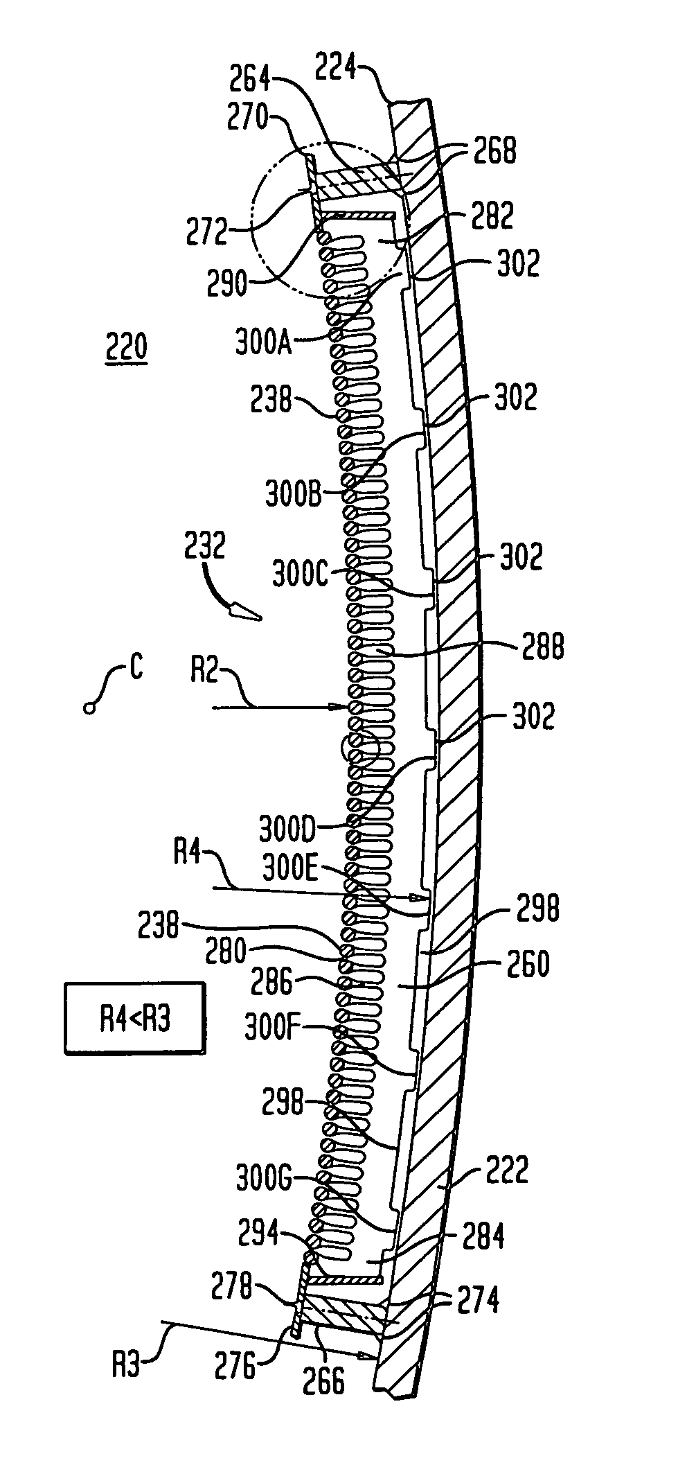
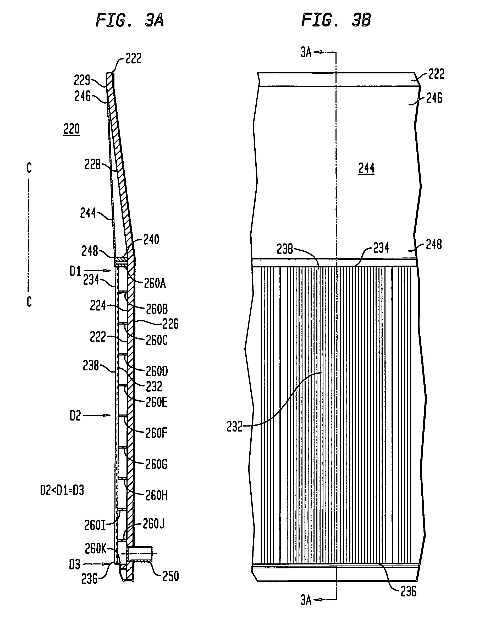
[0049]FIGS. 3A and 3B show a pulp digester 220 in accordance with certain preferred embodiments of the present invention. The pulp digester 220 desirably includes a vessel wall 222 with an interior surface 224 facing the inside of the vessel and an exterior surface 226 facing the outside of the vessel. The vessel wall 222 has a step out section 228 that diverges outwardly from an upstream stage 229 of the digester. The vessel wall 222 also has a straight section 230 located below the step out section 228. The vessel wall 222 has a longitudinal axis or centerline C-C, and the step out section 228 diverges outwardly from the centerline C-C for expanding the interior diameter of the vessel wall 222 between the upstream stage 229 and a downstream stage.

[0050]Referring to FIGS. 3A, 3B and 4, the digester 220 preferably includes a bar screen 232 having an upper end 234 and a lower end 236. The bar screen 232 desirably includes a plurality of vertically extending bars 238 that are spaced f...


PUM

PropertyMeasurementUnit
radius R1aaaaaaaaaa
radius R1aaaaaaaaaa
heightaaaaaaaaaa

Abstract

A pulp digester includes a vessel having an inlet, an outlet and a wall extending between the inlet and the outlet, the wall of the vessel having a curved interior surface. The digester includes a screen assembly positioned inside the vessel adjacent to the curved interior surface of the wall for removing liquid from pulp material. The screen assembly is movable relative to the curved interior surface of the vessel wall. The digester includes at least one support element permanently attached to the vessel wall for limiting movement of the screen assembly relative to the curved interior surface of the vessel wall. In certain embodiments, the at least one support, such as a ledge permanently attached to the vessel wall, supports a portion of the screen assembly. The screen assembly may have an inner face that is concave in a horizontal direction and convex in a vertical direction.

Description

CROSS REFERENCE TO RELATED APPLICATIONS[0001]This application claims the benefit of the filing date of U.S. Provisional Patent Application No. 60 / 583,885, filed Jun. 29, 2004, the disclosure of which is hereby incorporated herein by reference.BACKGROUND OF THE INVENTION[0002]The present application is generally directed to making pulp and is more specifically directed to screen assemblies for pulp digesters.[0003]Continuous digesters are used in the paper and pulp industry to remove lignin from wood chips. The digesters generally include a series of tubular reactors that are arranged in a vertical orientation. The digester is made up of a plurality of reaction and extraction stages for carrying out the pulp-making process in a specific sequence. In certain stages, chemicals are introduced into the digester for chemically treating the woodchips. These chemicals may include hydrosulfide and sodium hydroxide, commonly referred to as liquor. In other stages, the chemicals are removed fr...

Claims


Application Information

Patent Timeline
Patent Type & Authority Patents(United States)
IPC IPC(8): D21C7/00B07B1/00D21C7/14D21D5/02
CPCB07B1/00B07B1/18D21C7/14D21C7/00B07B1/4618
Inventor NYKANEN, TUOMOHERNESNIEMI, LASSE
Owner METSO PAPER PORI OY
Why Eureka
Try Eureka