The weights of the materials used in the construction are relatively heavy when compared to the weight of the floor
system or foundational materials resulting in a top-heavy structure with a high center of gravity.
This is contrary to good
engineering practice wherein it is known that a heavy foundation is needed to overcome the overturning, uplift and sliding forces exerted by high winds.
Because of the lightweight of the steel trailer
bed, and other foundational elements, there is little resistance to high wind loads and the building can easily be blown off of the concrete piers during high winds.
Although the manufacturers claim that the tie down straps adequately withstand the wind loads, it is well known that conventional manufactured buildings are not safe for habitation during high windstorms.
Although the tie down strap system offers some improvement in the structural strength of the building, it does not achieve the degree of structural strength that is needed to withstand hurricane force winds or that would be achieved with a floor system or foundation that is heavier than the structure above.
Because the walls are constructed with wood studs and are insulated with fiberglass insulation installed into a 4-inch thick cavity there are two
resultant deficiencies.
The most obvious deficiency is the highly flammable wood construction.
These buildings burn very fast and are a
fire hazard for the occupants.
Generally it is not possible to achieve an insulation or R-value greater than an R-11 with the 4-inch
thick wall.
These buildings are generally not very energy efficient.
Walls constructed with wooden materials are flexible and do not achieve the structural strength that can be achieved with other building materials such as steel, concrete or composite building panels.
This places limits on the wind loads that a wood stud wall can withstand.
This increases the cost of construction and consumes more of our precious
natural resource.
There are three problems inherent in this design.
The first problem is with the excessive amount of heat that is known to build up inside the cavity.
This places an excessive load on the
air conditioning system and is not an energy efficient design.
The second problem is with the uplift forces exerted on a roof truss system during windstorms.
It is well known that roof systems that are not made an integral and structural part of the overall
building envelope can be blown off and separated from the building during high winds.
Although these devices offer some resistance to uplift forces, it is generally known that this remains a weak part of the overall structure.
The third problem is that most roof trusses are constructed with wooden materials.
Roof trusses constructed with wooden materials are flexible and do not achieve the structural strength that can be achieved with other building materials such as steel, concrete or composite building panels.
This places limits on the wind loads that a roof truss can withstand.
This increases the cost of construction and consumes more of our precious
natural resource.
This floor system is relatively lightweight and does not achieve the structural strength that is found with a concrete floor.
A wooden floor system is relatively flexible and cannot support the weight of heavy objects such as refrigerators, dressers and other
interior furnishings.
Over time, these floor systems have a tendency to warp or bow from the furniture and other dead and live loads placed upon them.
There are limitations with this design because the hand made bent
metal shapes cannot be made in long lengths and are not structurally strong.
They cannot be made with in integral
thermal break and a multitude of screws are required to connect the
metal shapes to the thin
skin of the building panel.
The
assembly design depicted in the Hesser patent is labor intensive, which results in excessive cost for material fabrication and erection.
The Hesser design is not structurally strong because the
metal shape itself does not control the positive and negative wind loads exerted on a building.
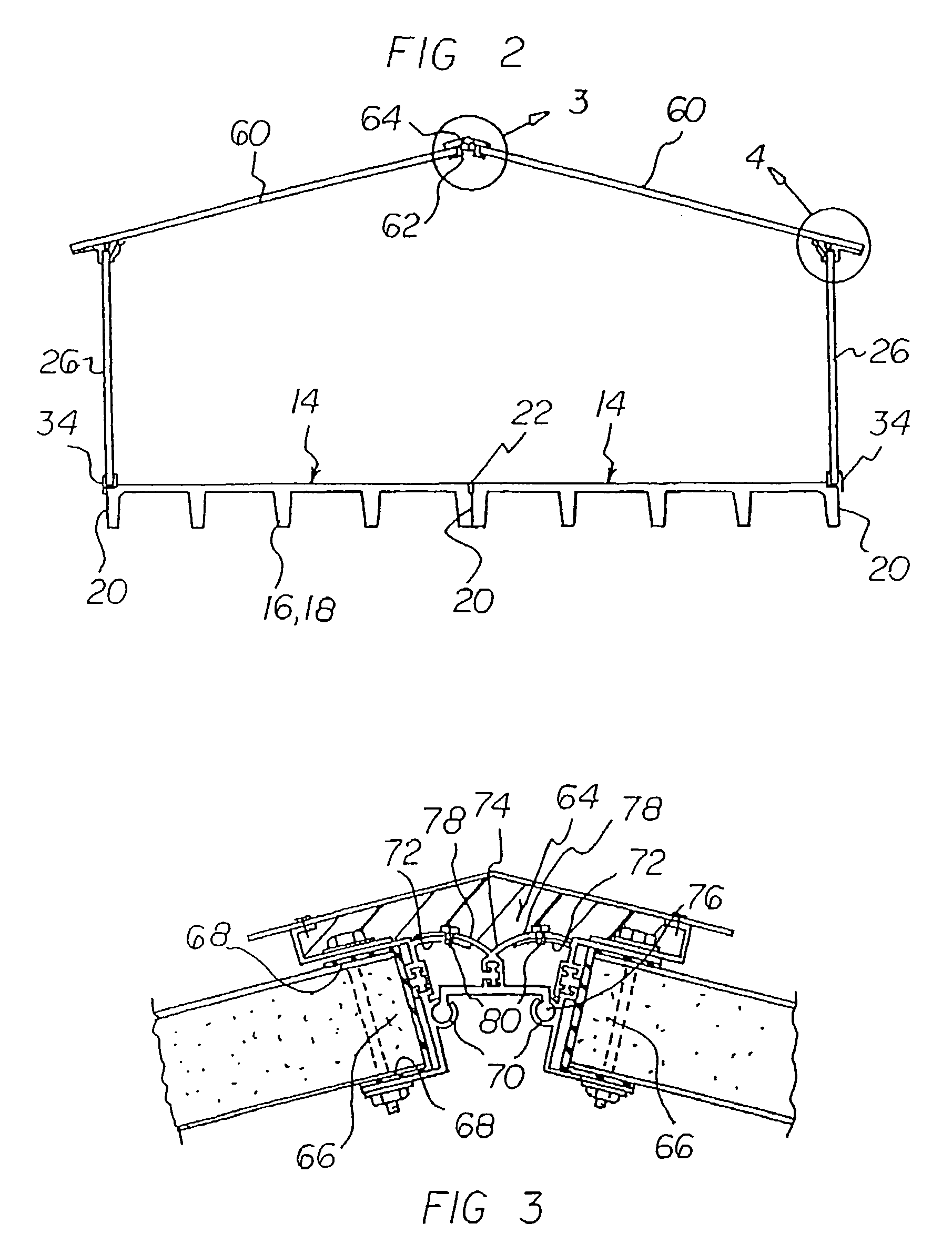
Hesser does not teach an extruded aluminum connector system that can be manufactured in long lengths.
Hesser does not teach an extruded aluminum connector system that includes an integral
thermal break and that is adjustable to accommodate various roof pitches and vertical wall angles.
Hesser does not teach an extruded aluminum connector system that is connected to the building panels with through bolts or that control the positive and negative wind loads through the connector itself.
Hesser does not teach a manufactured building system that can be transported on a self-trailering multi-stemmed concrete floor system.
This method of reinforcing a building panel is costly, due to higher material costs, and labor intensive, due to inserting the pieces by hand.
The method of constructing the pre-cast concrete slab depicted in Davenport uses an excessive amount of steel that is all placed by hand.
This results in excessive material and labor costs.
Furthermore, the steel bottom channels are exposed which makes the support frame susceptible to
rust and
corrosion.
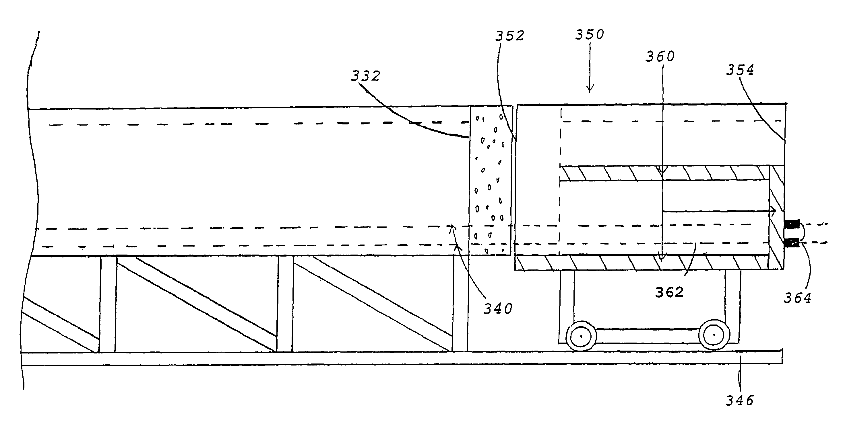
The wheels are not able to be located partially within the open spaces under the slab because of the multitude of cross beams, purlins and ribs formed to provide lateral support of the concrete.
This causes the center of gravity to be higher than is desirable and limits the overall building height for passing under bridges and utility lines.
Davenport does not teach a multi-stemmed concrete floor that is manufactured by the pre-stressing method.
Davenport does not teach a multi-stemmed concrete floor that transfers all of the longitudinal live and dead loads to a reinforced diaphragm header.
Davenport does not teach a multi-stemmed concrete floor that is manufactured entirely of concrete and does not rely an exposed
steel frame for structural support.
Davenport does not teach a multi-stemmed concrete floor that is transported by attaching a wheel
assembly directly to the down turned stems.
Davenport does not teach a multi-stemmed concrete floor that is manufactured in a self-stressing steel form with a removable stressing block.
The
casting form depicted by Eubanks cannot be used to make a pre-stressed slab because the sides would collapse from the stress imposed by the stressing strands used in the pre-stressing method.
Also, the tensioning of the slab after it has been cast and while it is still in the form would cause the inside face of the outermost side and end stems to be tightly compressed against the form thereby causing the slab to bind against the form and making it impossible to remove.
This is why the Eubanks design never became commercially viable.
This is not desirable because the overall width of the slab that can be transported over the highway is limited by the DOT regulations for maximum allowable widths.
Eubanks does not teach a multi-stemmed concrete floor that has several longitudinal stems running in a parallel direction.
Eubanks does not teach a multi-stemmed concrete floor with a reinforced diaphragm header.
Eubanks does not teach a multi-stemmed concrete floor that does not require post-tensioning or pre-stressing in the lateral direction and that is entirely reinforced in the lateral direction through the reinforced diaphragm header.
Eubanks does not teach a multi-stemmed pre-stressed concrete floor that is manufactured in a self-stressing steel form.
Eubanks does not teach a multi-stemmed concrete floor that is manufactured in a steel form with permanently fixed long sides and a removable stressing block.
Eubanks does not teach a multi-stemmed concrete floor
casting form that relieves the compressive forces exerted on the
casting form with a compressible filler
assembly.
As can be seen with the cited patents, some attempts have been made to overcome the inherent problems and deficiencies found with conventional manufactured homes and school classrooms but none has solved the aforementioned deficiencies.
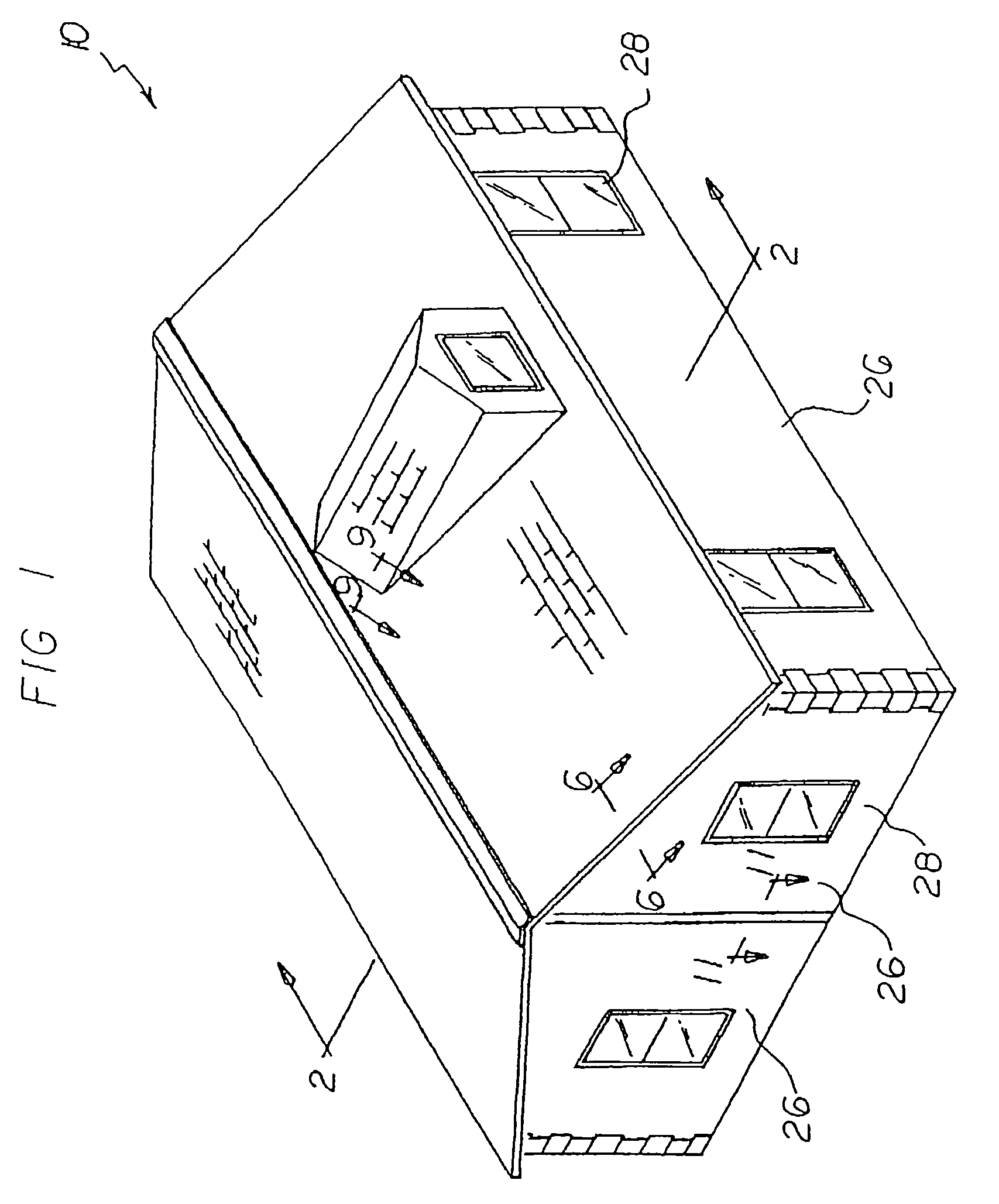
While these devices fulfill their respective, particular objectives and requirements, the aforementioned patents do not describe a manufactured building system that allows constructing partially prefabricated homes and school classrooms that can be easily assembled and constructed with a structural aluminum connector system and transported on a multi-stemmed pre-stressed concrete floor system.
It is well known that concrete is strong in compression but weak in tension.


