
Zero-Current Pulse With Constant Current Gradient For Interrupting A Direct Current

Active Publication Date: 2017-09-14
SIEMENS ENERGY GLOBAL GMBH & CO KG
View PDF2 Cites 7 Cited by
  • Summary
  • Abstract
  • Description
  • Claims
  • Application Information

AI Technical Summary

Benefits of technology

The patent describes an energy store that helps to compensate for a direct current by forming a resonant circuit when the switch is closed. The design uses chain links made of inductors, resistors, and capacitors, which allows for the creation of temporal dependencies and sequences. The use of RLC links allows for the creation of resonant circuits of different frequencies, resulting in zero-current pulses with different current gradients. The energy store comprises a plurality of energy storage elements that exhibit a triangular or ramp-shaped current curve, which also makes it easy to implement the desired current gradient. The technical effects of the patent are improved compensation for direct current flowing through an electrical component and efficient and reliable use of energy storage elements.

Problems solved by technology

If, however, the direct current that is to be compensated for is low, a zero-current crossing already occurs at an early point in time at which the current gradient of the zero-current pulse is still very high, possibly being too high.

Method used


Image

  • Zero-Current Pulse With Constant Current Gradient For Interrupting A Direct Current
  • Zero-Current Pulse With Constant Current Gradient For Interrupting A Direct Current

Examples


Embodiment Construction

AND DRAWINGS

[0024]The invention is explained in more detail below with reference to the attached drawings in terms of preferred exemplary embodiments.

[0025]Here

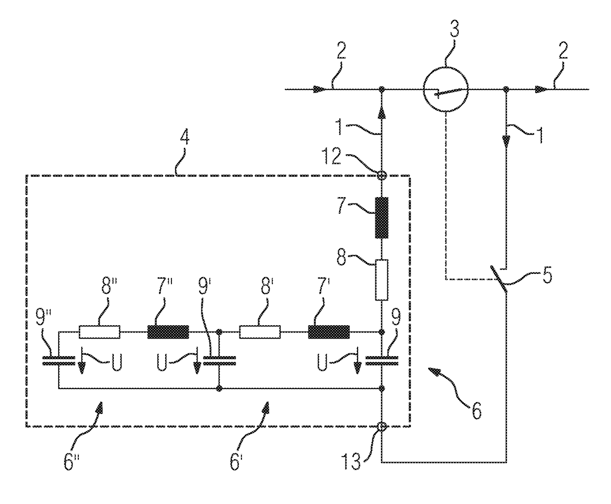
[0026]FIG. 1 shows an exemplary embodiment of the invention with a chain conductor of three chain links;

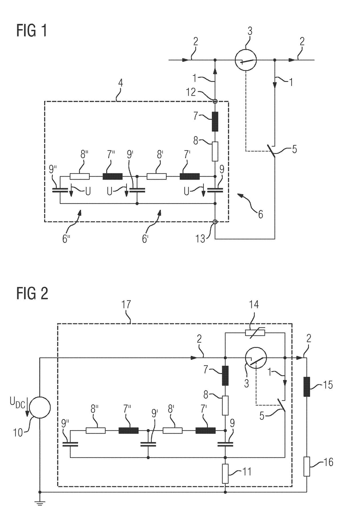
[0027]FIG. 2 shows an exemplary embodiment of a use of the invention for the construction of a direct current switch.

[0028]FIG. 1 shows a preferred exemplary embodiment of the invention. In FIG. 1 an arrangement for generating a zero-current pulse 1 for generating of a zero-current crossing in an electrical component 3 through which a direct current 2 flows can be seen, wherein the electrical component 3 is implemented as a vacuum interrupter.

[0029]The arrangement comprises an electrical energy store 4 with two poles 12, 13, which can be charged from a voltage source 10 illustrated in FIG. 2. The arrangement further, through the energy store 4, the electrical component 3 through which direct current flows, and a switch 5, c...


PUM


Abstract

A configuration for generating a zero current pulse for generating a zero current crossing in an electrical component through which a direct current flows, in particular a vacuum interrupter, includes a switch and an electrical energy storage device or store having two poles through which the electrical energy storage device can be charged by a voltage source. A loop can be formed by the energy storage device, the electrical component through which the direct current flows and the switch, so that the energy storage device can be discharged by closing the switch while generating a zero current pulse counter to the direct current across the electrical component. The energy storage device has a plurality of energy storage elements for mutual generation of a zero current pulse.

Description

[0001]The present invention relates to an arrangement for generating a zero-current pulse for generating a zero-current crossing in an electrical component through which a direct current flows, in particular a vacuum interrupter.PRIOR ART[0002]A vacuum interrupter is frequently employed as a load or power switch for currents in alternating current networks. To switch off the anode current or the switched current, the vacuum interrupter here requires a negative voltage which is provided by the negative half wave of the alternating voltage. In the case in which a direct current is to be interrupted, a current pulse, or a zero-current pulse, which can be superimposed onto the direct current in order to generate the necessary zero-current crossing, is required, as a result of the absence of a zero crossing.[0003]In the method known until now for generating an artificial zero-current crossing by means of a zero-current pulse, a simple resonant RLC circuit (a resonant circuit based on res...

Claims


Application Information

Patent Timeline
IPC IPC(8): H01H33/59H01H33/66
CPCH01H33/66H01H33/596H01H33/167
Inventor HEINZ, THOMAS
Owner SIEMENS ENERGY GLOBAL GMBH & CO KG
Learn More