
High performance strained silicon FinFETs device and method for forming same

a technology of fin field effect transistor and high-performance strained silicon, which is applied in the direction of semiconductor devices, electrical devices, transistors, etc., can solve the problems of difficult integration of strained silicon, difficult to control the thickness of the channel, and strained silicon channels that have not been demonstrated in devices as small as 50 nm, so as to improve device performance and yield. , the effect of improving the mobility of the channel

Active Publication Date: 2010-04-27
GLOBALFOUNDRIES US INC
View PDF6 Cites 51 Cited by
  • Summary
  • Abstract
  • Description
  • Claims
  • Application Information

AI Technical Summary

Benefits of technology

The present invention provides a method and structure for forming a silicon FinFET device with strained silicon under the gate. By using strained silicon on insulator structures, the device has improved channel mobility and performance compared to conventional all-silicon FinFET devices. Additionally, the strained silicon is less affected by threading defects, resulting in better yield in manufacturing. Overall, the invention provides a combination of strained silicon with a silicon FinFET, which has various advantages over conventional methods and structures.

Problems solved by technology

The fabrication of a FinFET is generally simpler than most other double-gate structures, although the channel thickness control is problematic in most known approaches (e.g., see U.S. Pat. No. 6,413,802; Yang-Kyu Choi et al., “Spacer FinFET: nanoscale double-gate CMOS technology for the terabit era”, Solid-State Electronics, 46, p.
However, such strained silicon channels have not been demonstrated for devices as small as 50 nm or less.
However, for FinFET devices, strained silicon has been difficult to integrate due to the geometry of the fin and the gate and the fabrication process.

Method used


Image

  • High performance strained silicon FinFETs device and method for forming same
  • High performance strained silicon FinFETs device and method for forming same
  • High performance strained silicon FinFETs device and method for forming same

Examples


second exemplary embodiment

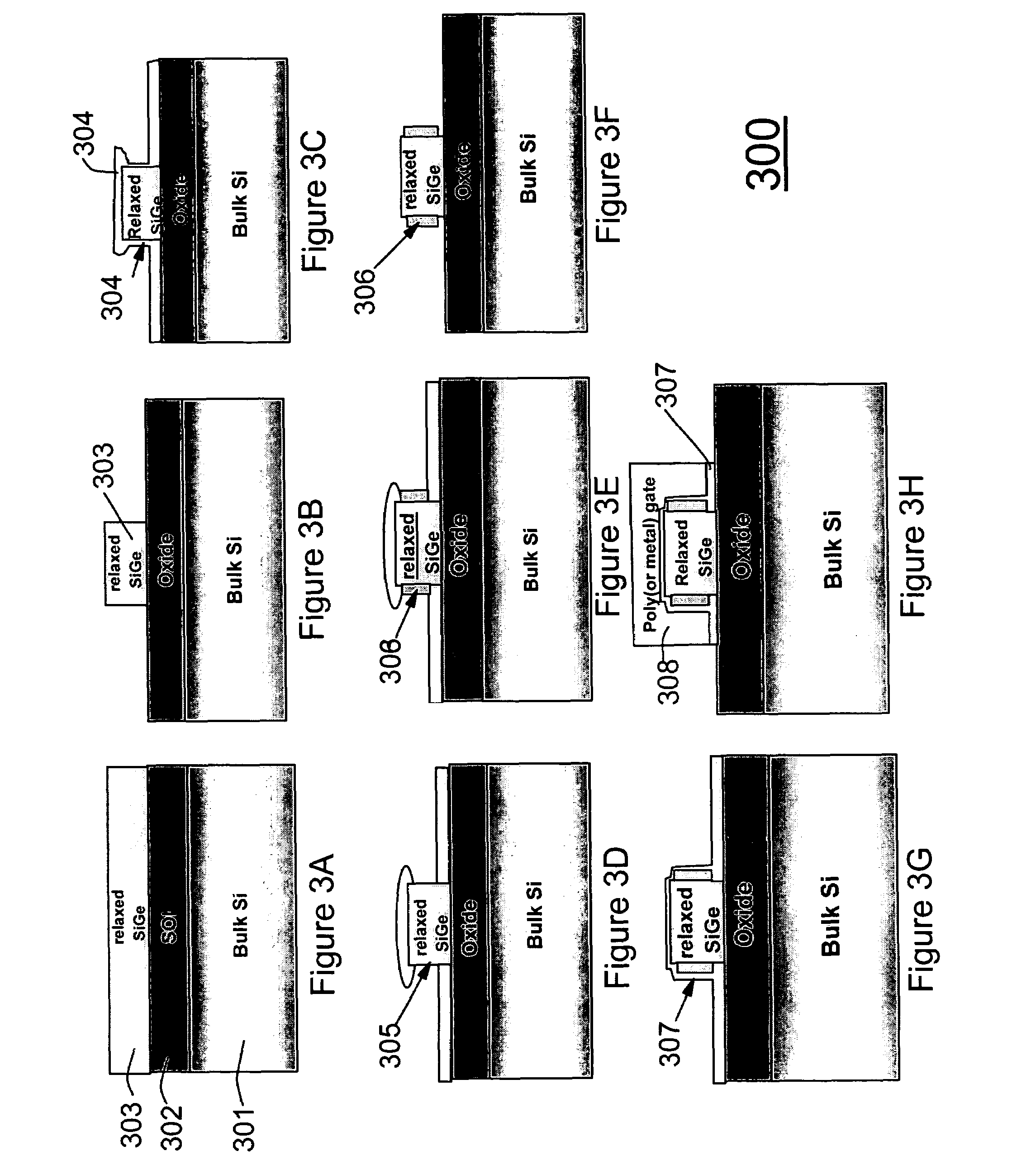
[0073]A second exemplary embodiment, as shown in FIGS. 4A-4E, is advantageous as it allows the invention to minimize the number of mask steps. Indeed, it allows the invention to avoid a mask step since as shown and described below, there is a fin oxide hard mask above, and an oxide layer below, the relaxed SiGe layer. It is noted that thin silicon (˜5-10 nm) from the SOI is removed after the SiGe Fin RIE.

[0074]As a result, the second exemplary embodiment provides a process which is automatically self-aligned, thereby providing a more simple and elegant method even for a small gate. Hence, this embodiment provides self-aligned masking for selective growth. Moreover, there is no need to remove the hard mask to dope the top of the structure, as the invention allows doping on the sides of the structure.

[0075]Turning now to FIGS. 4A-4E and the flowchart 450 of FIG. 4F, a process of forming a FinFET 400 according to the present invention is shown.

[0076]First, in FIG. 4A (and step 455 of t...


PUM

PropertyMeasurementUnit
widthaaaaaaaaaa
thicknessaaaaaaaaaa
thicknessaaaaaaaaaa

Abstract

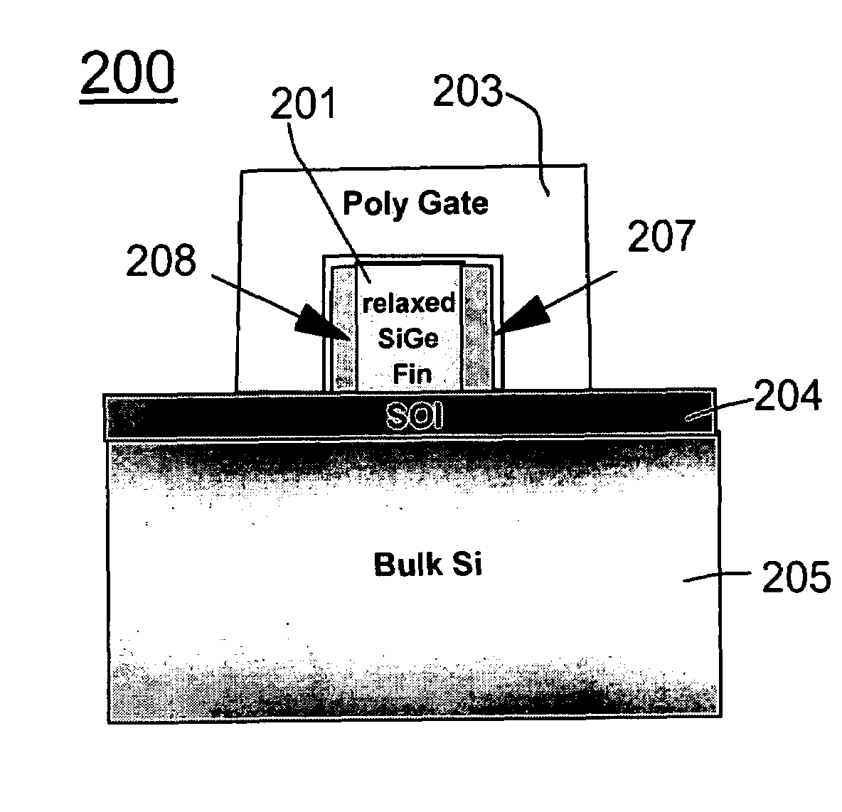
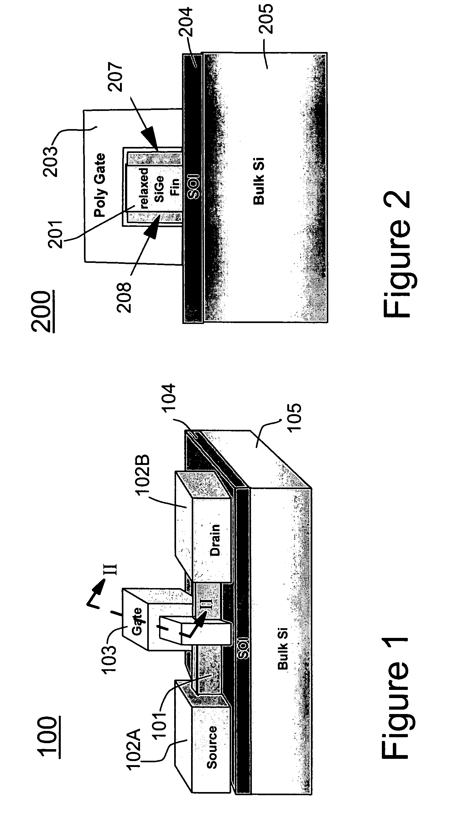
A strained Fin Field Effect Transistor (FinFET) (and method for forming the same) includes a relaxed first material having a sidewall, and a strained second material formed on the sidewall of the first material. The relaxed first material and the strained second material form a fin of the FinFET.

Description

BACKGROUND OF THE INVENTION[0001]1. Field of the Invention[0002]The present invention generally relates to a semiconductor device, and more particularly to a high performance strained silicon, Fin field effect transistor (FinFET) device.[0003]2. Description of the Related Art[0004]Fin FETs are considered promising candidates for complementary metal oxide semiconductor (CMOS) device scaling (e.g., see Hu Chenming et al., U.S. Pat. No. 6,413,802 entitled “FinFET transistor structures having a double gate channel extending vertically from a substrate and methods of manufacture”).[0005]Indeed, FinFETs are a type of double gate structure which offer high silicon current delivery than single gate devices. Further, FinFETs improve the short channel characteristics of the device and are easier to scale down from.[0006]The fabrication of a FinFET is generally simpler than most other double-gate structures, although the channel thickness control is problematic in most known approaches (e.g., ...

Claims


Application Information

Patent Timeline
Patent Type & Authority Patents(United States)
IPC IPC(8): H01L29/06H01L31/072H01L21/336H01L21/84H01L27/01H01L27/12H01L29/786
CPCH01L21/845H01L29/785H01L29/66795H01L27/1211
Inventor BEDELL, STEPHEN W.CHAN, KEVIN K.CHIDAMBARRAO, DURESETICHRISTIANSON, SILKE H.CHU, JACK O.DOMENICUCCI, ANTHONY G.LEE, KAM-LEUNGMOCUTA, ANDA C.OTT, JOHN A.OUYANG, QIQING C.
Owner GLOBALFOUNDRIES US INC
Learn More