
Thermal displacement-based radiation detector of high sensitivity

a radiation detector and thermal displacement technology, applied in the field of radiation detection devices, can solve the problems of bulky radiation detection devices with high power consumption, major deficiencies in technology, and inability to detect high-sensitivity infrared cameras

Inactive Publication Date: 2010-04-27
FLIR COMML SYST
View PDF17 Cites 20 Cited by
  • Summary
  • Abstract
  • Description
  • Claims
  • Application Information

AI Technical Summary

Benefits of technology

The present invention relates to a micro mirror device that can detect infrared radiation. The device includes an illumination reflector, a thermal pad, and a cantilever support. When the thermal pad is exposed to infrared radiation, the cantilever support bends, tilting the illumination reflector and causing it to reflect the infrared radiation. The invention also includes an infrared radiation sensing device with multiple micro mirror devices attached to a substrate via a thermally deformable cantilever beam. The device can detect infrared radiation of different wavelengths and can be used in a radiation detector. The technical effects of the invention include improved detection and spatial resolution of infrared radiation.

Problems solved by technology

However, these technologies have major deficiencies.
In the present state of the art, the sensitivity of an infrared camera may be fundamentally limited by electron thermal noise.
Cooling may be used to mitigate this limitation, but this additional complexity results in a bulky radiation detection device with high power consumption.
Moreover, the fabrication of these devices is intrinsically hampered by the need for an electrical interconnect to each pixel as well as integrated scanning readout electronics.
All of these factors have kept the cost prohibitively high for many commercial applications, as well as making the detectors expensive to produce and difficult to scale in array size (i.e., resolution) due to low fabrication yield of the detection sensor.
However, the requirement of providing an electrical readout contact to the sensor element may reduce sensitivity as a result of thermal signal leak.
'124 and in U.S. Pat. No. 5,929,440 issued to Fisher, use bimaterial cantilevers directly as the sensors are intrinsically and significantly poor in sensitivity; rendering them impractical for commercial applications.
In these imager designs, bimaterial cantilevers are exposed to thermal radiation that heats up the cantilevers, leading in turn to bending as a result of the thermal expansion mismatch of the two cantilever materials.
However, early designs have had poor radiation absorption efficiency and large sensor mass that lead to inefficient thermal bending devices.
This design may also leave the sensor component directly exposed to environmental temperature fluctuation and hence cannot be used as “uncooled.”
However, the design lacks many features that are important for practical applications.
No semiconductor materials known today can provide such sensitivity improvement without sacrificing responses time.
Low thermal sensitivity has also limited the achievable dynamic range in the current state of the art.

Method used


Image

  • Thermal displacement-based radiation detector of high sensitivity
  • Thermal displacement-based radiation detector of high sensitivity
  • Thermal displacement-based radiation detector of high sensitivity

Examples


Embodiment Construction

[0025]The following detailed description is of the best currently contemplated modes of carrying out the invention. The description is not to be taken in a limiting sense, but is made merely for the purpose of illustrating the general principles of the invention, since the scope of the invention is best defined by the appended claims.

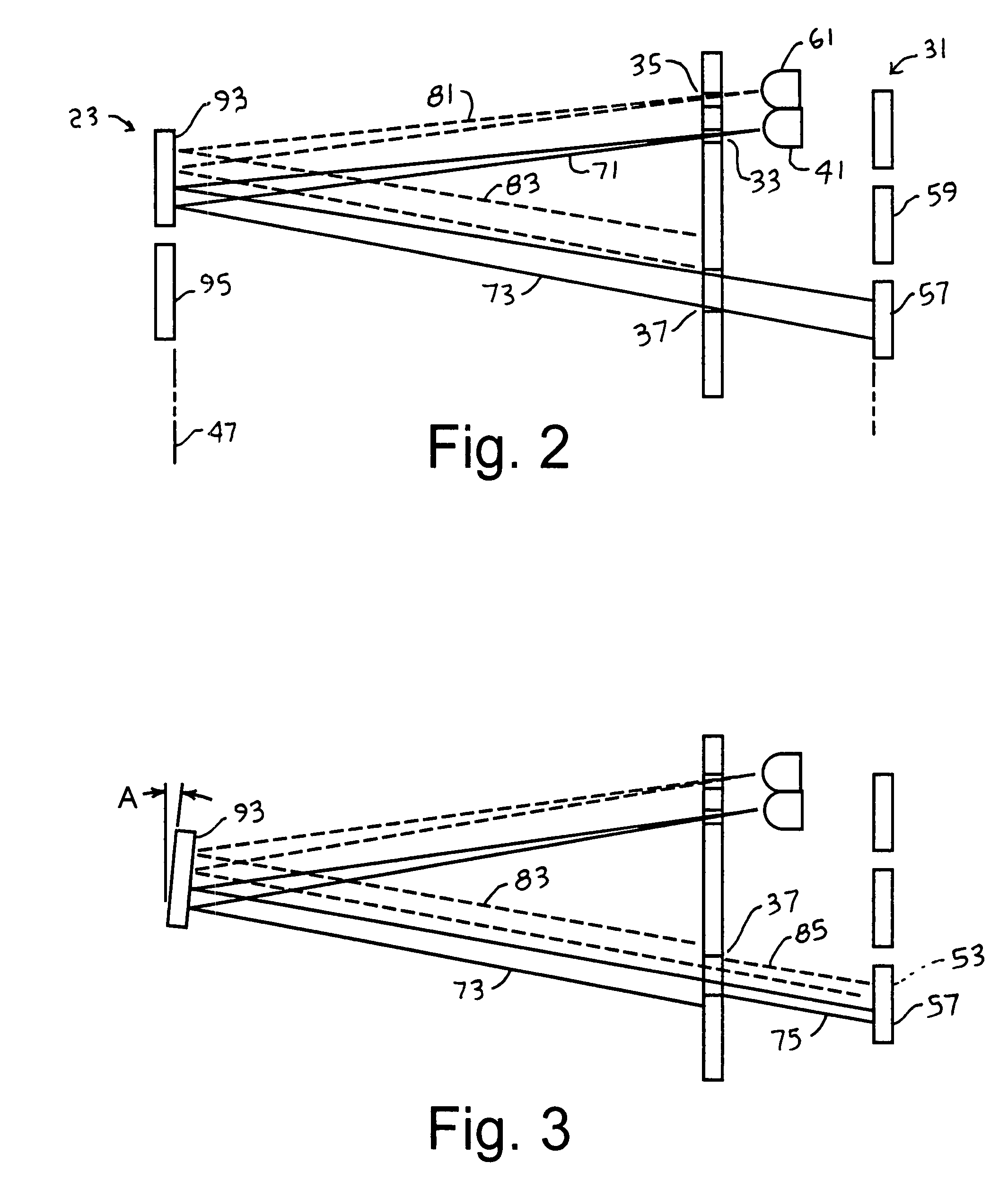
[0026]The present invention is related to an optical readout that has significantly larger dynamic temperature sensing range than that of conventional radiation detectors. The innovation is based on the incorporation of sensitive polymer molecular material with a highly efficient micro machined thermal mechanical micro mirror array that directly converts an incident infrared image into a visible image. This performance feature is highly desirable for thermograph and fire-fighting applications, for example. For many applications, including fire fighting, there is a need for a large dynamic range that often exceeds 400 C.°. The disclosed design functions ...


PUM


Abstract

A radiation detector comprises an infrared radiation sensing micro mirror array, where each micro mirror is supported with a deformable cantilever beam having an organic layer for increased dynamic range. The radiation detector includes two or more sources of optical radiation for irradiating the micro mirror array, an image sensor array for receiving optical reflection from the micro mirror array, and an aperture plate for (i) spatially restricting optical radiation reaching the micro mirror array and (ii) spatially restricting reflected optical reflection reaching the image sensor array.

Description

CROSS-REFERENCE TO RELATED APPLICATION[0001]The present Application claims the benefit of Provisional Patent Application No. 60 / 776,725 entitled “Thermal displacement based radiation detector,” filed 27 Feb. 2006 and incorporated by reference herein in its entirety.BACKGROUND OF THE INVENTION[0002]1. Field of Invention[0003]The present invention relates to radiation detection devices and, in particular, to an extended range thermal displacement-based radiation detecting device.[0004]2. Description of the Background Art[0005]Conventional radiation detection devices, such as thermal cameras, may operate using a thermo-electric mechanism to detect radiation signals. For example, an infrared signal distribution may be directed onto a semiconductor imaging device and current or voltage changes may be measured to indicate a temperature rise in each pixel. However, these technologies have major deficiencies. In the present state of the art, the sensitivity of an infrared camera may be fund...

Claims


Application Information

Patent Timeline
Patent Type & Authority Patents(United States)
IPC IPC(8): B41J2/05
CPCG01J5/08G01J5/40G01J5/0896G01J5/0831
Inventor ZHAO, JINGZHANG, LEI
Owner FLIR COMML SYST
Learn More