
Light guide illumination device appearing uniform in brightness along its length

a technology of illumination device and light guide, which is applied in the direction of waveguide, lighting and heating apparatus, instruments, etc., can solve the problems of difficult to achieve high brightness by this extraction technique, difficult to control the amount of light radially extracted, and less efficient at extracting ligh

Inactive Publication Date: 2005-03-08
3M INNOVATIVE PROPERTIES CO
View PDF43 Cites 52 Cited by
  • Summary
  • Abstract
  • Description
  • Claims
  • Application Information

AI Technical Summary

Benefits of technology

The present invention solves this problem by employing optical quality extraction structures for performing light extraction and a diffuse reflective layer for diffusely reflecting the ex

Problems solved by technology

Unfortunately, because the roughened areas are not of optical quality but are rather random in size and orientation, it is difficult to control the amount of light radially extracted from the fiber and thus in general it is difficult to achieve high levels of brightness by this extraction technique.
Thus, while such roughened areas facilitate the diffusion of light, they are less efficient at extracting the light than light extraction structures formed from optical quality surfaces.
Unfortunately, a device using such an extraction technique typically appears to have discrete, non-uniform areas of brightness along its length.

Method used


Image

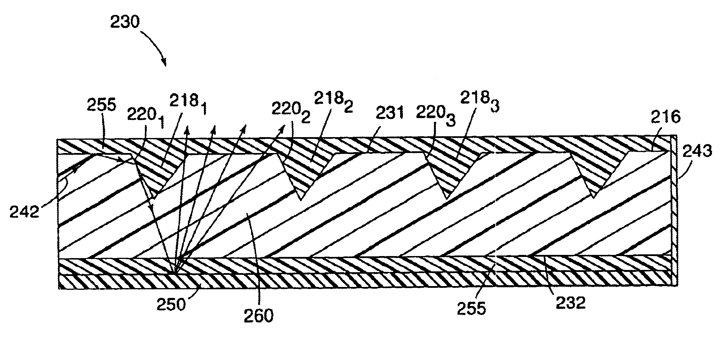
  • Light guide illumination device appearing uniform in brightness along its length
  • Light guide illumination device appearing uniform in brightness along its length
  • Light guide illumination device appearing uniform in brightness along its length

Examples


Embodiment Construction

Light Guide Illumination Device

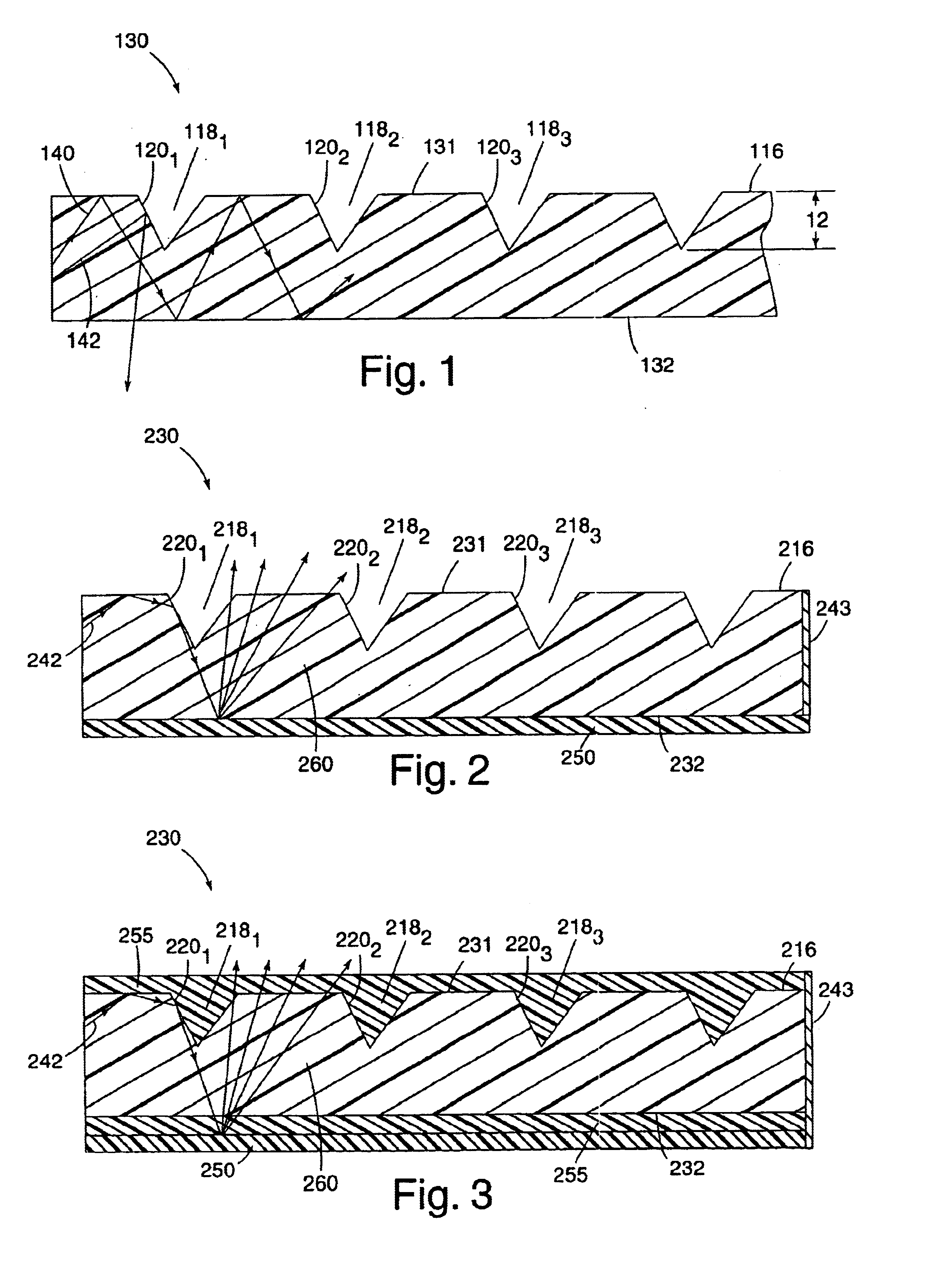
FIG. 1 depicts a side view of a portion of a known illumination device. The illumination device is formed from a light guide 130 having a light guide core and a cladding surrounding the core. The refractive index of the core is greater than the refractive index of the cladding so that the light traveling through or along or down the light guide is reflected at the surfaces of the light guide with minimal losses in accordance with the principles of total internal reflection. In the simplest case, the cladding may be ambient air, thus avoiding the need for a separate cladding material. The illumination device shown in FIG. 1 does not employ a cladding material.

Light guide 130 has a circumferential surface 116 that includes one or more light extraction structures 1181, 1182, 1183, . . . that are formed therein. Circumferential surface 116 includes a first surface portion 131, which contain light extraction structures 1811, 1182, 1183, . . . , and a second...


PUM


Abstract

An illumination device that is relatively bright and uniform in appearance includes a light guide, which has a light guide core having an optically smooth surface for propagating light therethrough. A light emitting region, which extends along a portion of the core, includes at least one light extraction structure located along the optically smooth surface of the light guide core. The light extraction structure, which includes an optically reflective surface extending into the light guide core, is oriented to reflect light at an angle less than a critical angle necessary for light to propagate through the light guide core. A diffuse reflective material is disposed around at least a portion of the light guide. The diffuse reflective material directs at least a portion of the light reflected by the light extraction structure back through the light guide so that light is emitted through the light emitting region of the optically smooth surface.

Description

FIELD OF THE INVENTIONThe present invention relates generally to an illumination device, and more particularly, to a light guide illumination device having optical quality light extraction structures and a diffuse reflective material to provide a light guide that appears substantially uniform in brightness along its length.BACKGROUND OF THE INVENTIONOptically transmissive materials, such as glass or polymers may be used as a light guide to propagate light. A light guide typically includes at least one surface adapted to receive light from a light source and an optically smooth surface for reflecting light propagating through the light guide. Common examples of light guides include optical fibers traditionally used in the data communication industry and more recently light fibers used for illumination purposes. For example, U.S. Pat. No. 5,432,876 (the '876 patent) discloses one such illumination device employing light fibers. In this device, light may be injected into at least one e...

Claims


Application Information

Patent Timeline
IPC IPC(8): F21V8/00G02B6/00F21S2/00G09F13/00
CPCG02B6/001G02B6/0065G02B6/0055G02B6/0038Y10S385/901
Inventor LUNDIN, DAVID J.
Owner 3M INNOVATIVE PROPERTIES CO
Learn More