
Method and apparatus for frequency discriminator and data demodulation in frequency lock loop of digital code division multiple access (CDMA) receivers

a data demodulator and frequency discriminator technology, applied in the field of digital receivers for spread spectrum signals, can solve the problems of loss of strong signal tracking, more frequency error tolerable, data demodulation is more complicated in fll than in pll, etc., and achieve the effect of improving the estimation of frequency errors

Inactive Publication Date: 2010-04-20
CSR TECH INC
View PDF10 Cites 16 Cited by
  • Summary
  • Abstract
  • Description
  • Claims
  • Application Information

AI Technical Summary

Benefits of technology

[0019]Briefly, an embodiment of the present invention includes a method and apparatus for improving estimation of frequency error in a frequency locked loop (FLL) and including receiving a predetermined number of samples of a Ika, Qka, Ikb and Qkb, constructing longer coherently integrated samples Ik and Qk, calculating phase angles, Φkab, Φkba, Φk, of samples, calculating phase rotations, ΔΦkab, ΔΦkba, ΔΦk using the computed phase angle, c

Problems solved by technology

A Costas PLL offers accurate carrier phase measurements and easy data demodulation mechanism, but the PLL is sensitive to dynamics stress potentially causing it to even lose tracking of a strong signal.
Unfortunately, data demodulation is more complicated in a FLL than in a PLL.
The larger the detection range, the more frequency error is tolerable for a receiver to handoff from acquisition to tracking.
However, phase angle difference quantities are usually noisier than the phase angle measurements themselves, which also result in noisy frequency error estimate.
This is one of the problems associated with prior art techniques of estimating the frequency error accuracy.
Since the two sampling times ta and tb are within the same bit interval, this frequency error estimation method is insensitive to bit transitions; however, the variance of phase difference (Φb−Φa) generally is twice as the variance of the phase Φa or Φb, which leads to a noisy frequency error estimate.
The π carrier phase shifts, caused by unknown bit transitions, make data modulation difficult in an FLL.

Method used


Image

  • Method and apparatus for frequency discriminator and data demodulation in frequency lock loop of digital code division multiple access (CDMA) receivers
  • Method and apparatus for frequency discriminator and data demodulation in frequency lock loop of digital code division multiple access (CDMA) receivers
  • Method and apparatus for frequency discriminator and data demodulation in frequency lock loop of digital code division multiple access (CDMA) receivers

Examples


Embodiment Construction

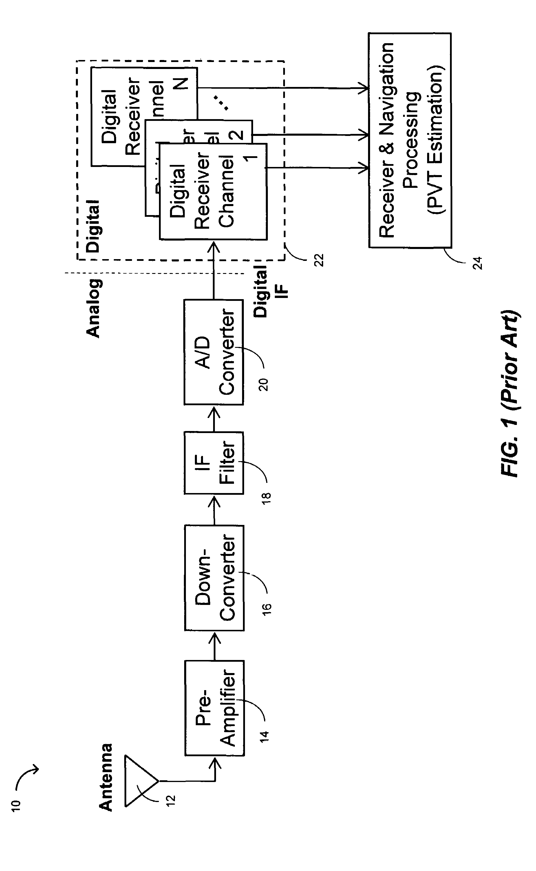
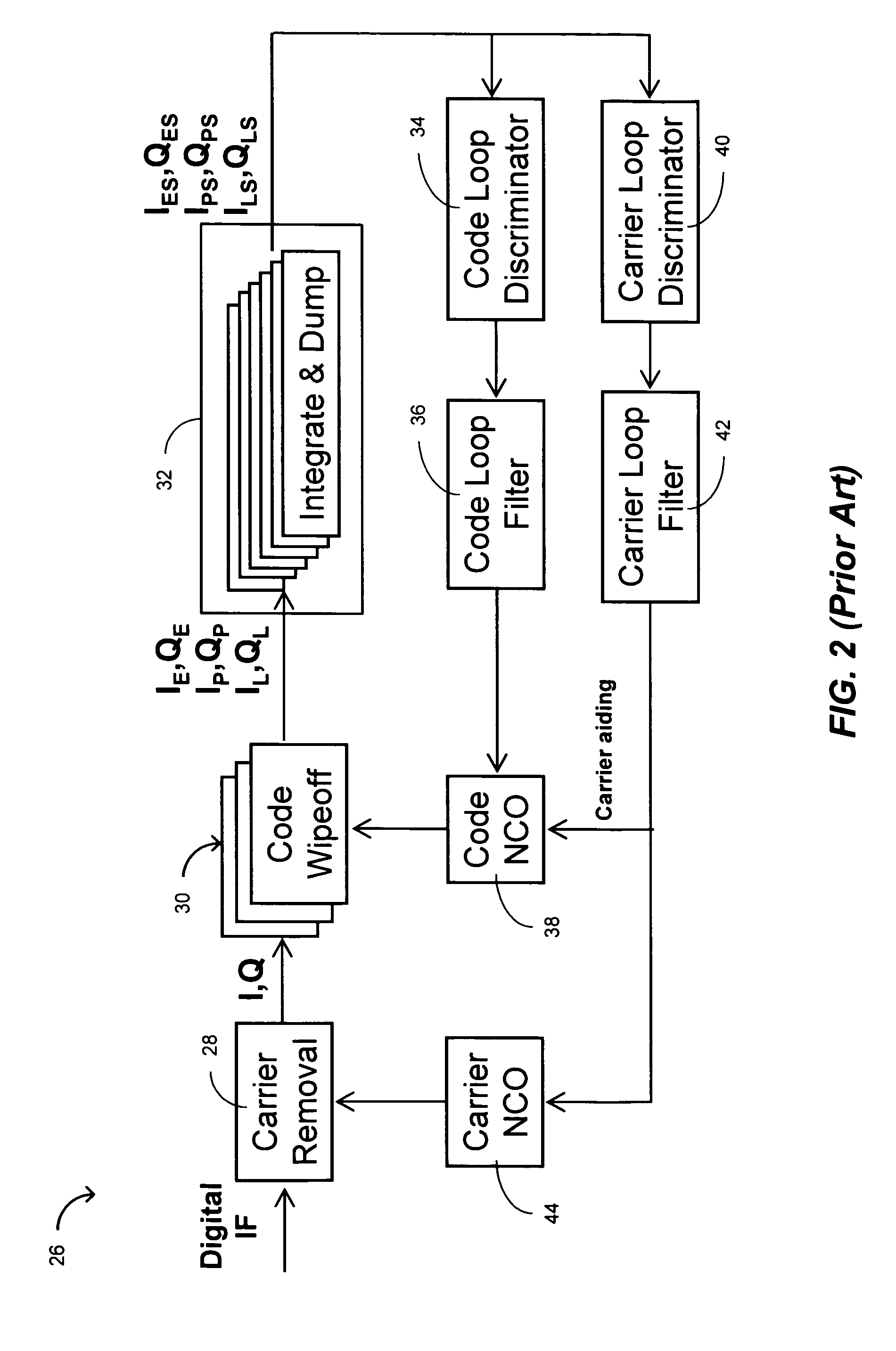
[0040]In one embodiment of the present invention, a method of estimating the frequency error in an FLL substantially improves the quality of frequency error estimates to decrease the bit error rate in data demodulation and increase the signal tracking sensitivity.

[0041]In another embodiment of the present invention, a method of demodulating GPS navigation data bits for GPS receivers with the carrier tracking loop implemented as an FLL is disclosed. An FLL update time, longer than a one-bit time duration, such as 100-ms, is used so that a FLL discriminator can estimate the frequency error based on multiple shorter-time (e.g., 10 ms and 20 ms) coherent integration samples by an averaging method. This FLL update rate depends on specific applications and different receiver designs. In most GPS applications, an update rate of every 100 ms or 200 ms is currently considered a reasonable number to meet both the dynamic and the sensitivity requirements and is accordingly used herein as examp...


PUM


Abstract

An embodiment and method of the present invention includes a frequency lock loop (FLL) having an improved frequency error estimation and a low bit error rate (BER) in data demodulation by calculating and using an improved averaged phase rotation using ‘valid’ phase rotation samples.

Description

BACKGROUND OF THE INVENTION[0001]1. Field of the Invention[0002]The present invention relates generally to digital receivers for spread spectrum signals such as those used in Global Positioning System (GPS), and more particularly to a frequency discriminator and data demodulation techniques used in the carrier frequency lock loop (FLL) of digital code division multiple access (CDMA) spread spectrum receivers.[0003]2. Description of the Prior Art[0004]Global Positioning System (GPS) is a satellite-based radio navigation system. Each GPS satellite, also called space vehicle (SV), continuously transmits time-tagged spread-spectrum signals on two L-band carrier frequencies. Carriers are used for modulation of GPS signals, to be transmitted. “Carrier” and “carrier signal” are used interchangeably herein. Briefly, carrier is a sine / cosine wave characterized by its frequency. “Carriers” or “carrier signals”, at a carrier frequency, as often referred to herein, are modulated by binary bits ...

Claims


Application Information

Patent Timeline
IPC IPC(8): H04L27/00H04L27/22
CPCG01S19/24G01S19/29H04L27/0014H04B1/707H04L2027/0069H04L2027/0053
Inventor YUAN, XIANGXIE, GANG
Owner CSR TECH INC
Learn More