
Condenser microphone

a condenser microphone and microphone technology, applied in the direction of transducer acoustic reaction prevention, transducer details, electrical transducers, etc., can solve the problems of modulation down converter interrupting an input voltage, infrared proximity sensor may malfunction,

Inactive Publication Date: 2010-04-13
AUDIO-TECHNICA
View PDF4 Cites 7 Cited by
  • Summary
  • Abstract
  • Description
  • Claims
  • Application Information

AI Technical Summary

Benefits of technology

The present invention provides a condenser microphone with a proximity sensor that prevents noise and malfunctions caused by the AC component used to light the infrared light emitting diode. The microphone operates using a predetermined DC power source and includes two DC-DC converters connected in parallel with the DC power source. One converter supplies power to the infrared light emitting diode and the oscillation circuit, while the other converter supplies power to the infrared photodetector. The lighting frequency of the infrared light emitting diode is different from the operating frequency of the DC-DC converters to prevent interference with noise. A switched capacitor type voltage converter is used as the DC-DC converter to prevent noise from mixing into the power supply voltage of the microphone.

Problems solved by technology

However, the infrared proximity sensor may malfunction when the speaker is at a standstill or owing to external light, a variation in temperature, or the like.
In this regard, a phantom power source generally used for condenser microphones provides an excessively high voltage.
However, the pulse width modulation down converter interrupts an input voltage.
Consequently, the pulse width modulation down converter makes noise of a very high level in connection with the switching.
The noise may be mixed into the power supply voltage to increase the amount of noise from the microphone.
As a result, noise may be output.
However, when the AC component used to light the infrared light emitting diode is superimposed on the power supply to the infrared photodetector, the infrared photodetector malfunctions as if it received an infrared beam, because of its high sensitivity.

Method used


Image

  • Condenser microphone
  • Condenser microphone

Examples


Embodiment Construction

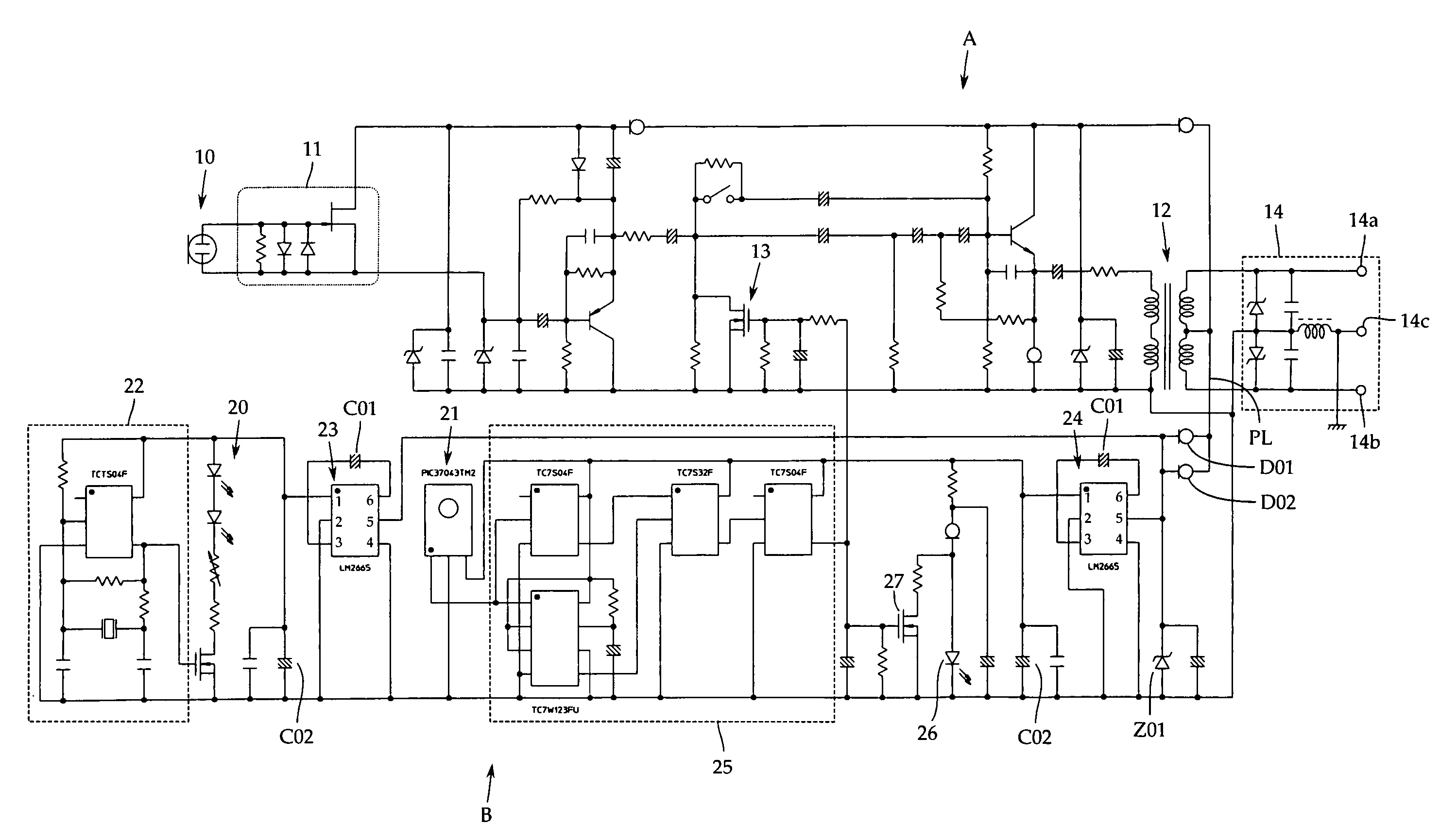
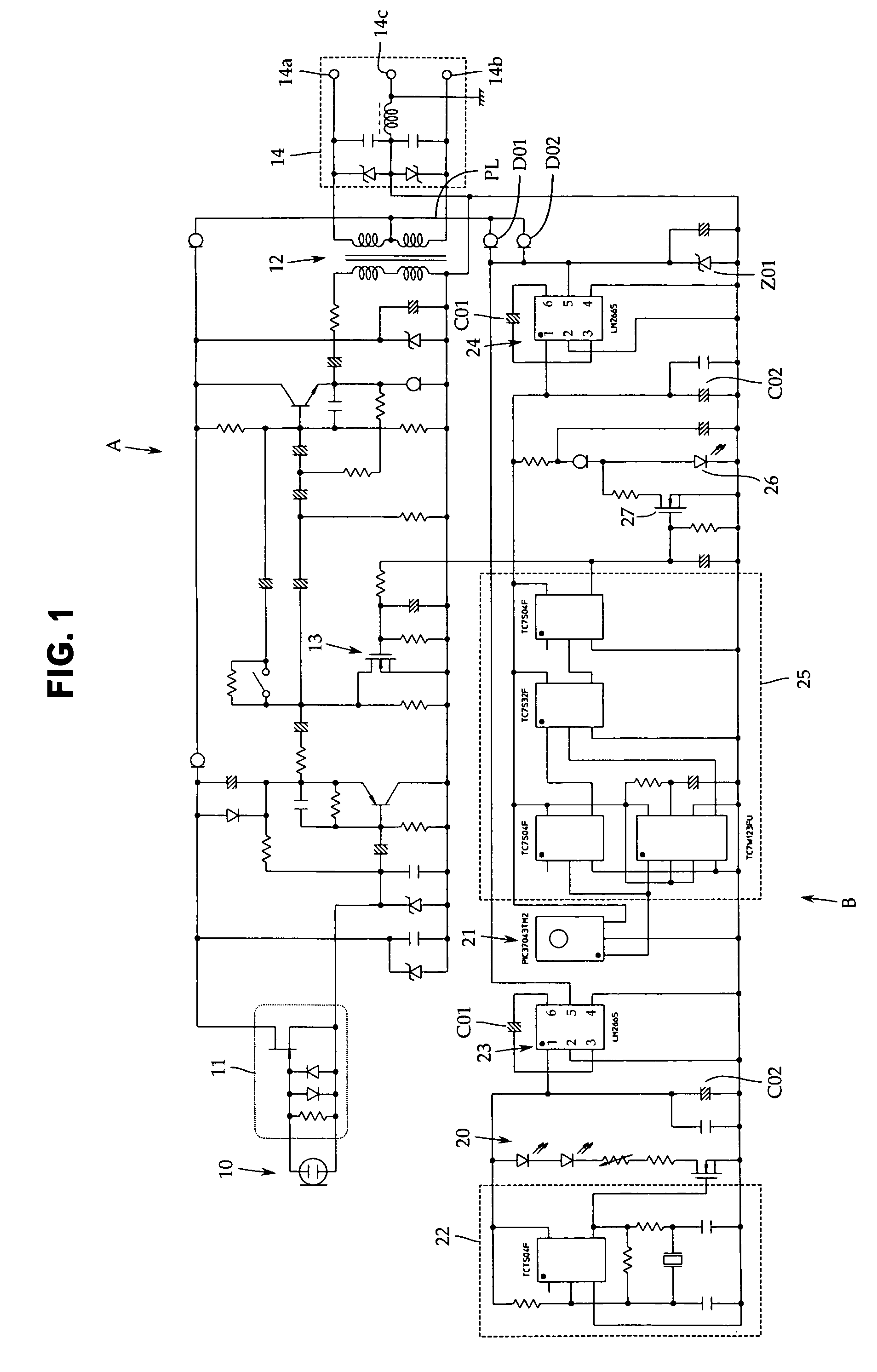
[0018]Now, an embodiment of the present invention will be described with reference to FIG. 1. However, the present invention is not limited to this. FIG. 1 is a detailed circuit diagram of a condenser microphone. Here, description will focus on a power source section of an infrared proximity sensor which relates to the present invention.

[0019]FIG. 1 shows a sound signal output circuit A in a microphone having a condenser microphone unit 10, and a proximity sensor circuit B having an infrared light emitting diode 20 and an infrared photodetector 21. The proximity sensor circuit B is provided with an oscillation circuit 22 that lights the infrared light emitting diode 20 using an AC component. The infrared photodetector 21 is turned to its lighting frequency to output a sensing signal.

[0020]The condenser microphone unit 10 may be, for example, a gooseneck microphone or a stand type microphone and may be installed in a predetermined place. The proximity sensor may be provided in a hous...


PUM


Abstract

The present invention provides a condenser microphone having a proximity sensor consisting of an infrared light emitting diode and an infrared photodetector, the condenser microphone preventing the occurrence of noise and the malfunctioning of the infrared photodetector when the infrared light emitting diode is lighted using an AC component. Specifically, the present invention provides a condenser microphone operated using a predetermined DC power source; an infrared light emitting diode 20 is lighted at a predetermined frequency by an oscillation circuit 22 using an AC component, and a microphone output is turned on and off by an output signal from the infrared photodetector 21 which is tuned to the predetermined frequency. The condenser microphone further includes two DC-DC converters 23 and 24 connected in parallel with the DC power source. One 23 of the DC-DC converters 23 supplies power to the infrared light emitting diode 20 and the oscillation circuit 22. The other DC-DC converter 24 supplies power to the infrared photodetector 21.

Description

TECHNICAL FIELD[0001]The present invention relates to a condenser microphone, and more specifically, to a condenser microphone comprising a proximity sensor consisting of an infrared light emitting diode and an infrared photodetector.BACKGROUND ART[0002]Condenser microphones have various applications. For example, some condenser microphones are installed on a speech table in a conference room or a church. These condenser microphones comprise a proximity sensor that turns on a microphone output only when there is a speaker standing in front of the speech table; the proximity sensor turns off the microphone output when there is no speaker standing in front of the speech table.[0003]Proximity sensors are classified into a supersonic type, an electrostatic type, an infrared type, and the like. For microphones, the infrared proximity sensor is generally used, which consists of an infrared light emitting diode not serving as a noise source and an infrared photodetector.[0004]However, the ...

Claims


Application Information

Patent Timeline
Patent Type & Authority Patents(United States)
IPC IPC(8): H04R3/00H04R1/00H04R25/00H04R3/02
CPCH04R19/04H04R1/04H04R3/00
Inventor AKINO, HIROSHI
Owner AUDIO-TECHNICA
Learn More