Plasma diagnostic apparatus and method
a technology of diagnostic apparatus and plasma, which is applied in the direction of testing/measurement of semiconductor/solid-state devices, instruments, and eavesdropping prevention circuits, etc., can solve the problems of inability to accurately measure current, inability to apply methods, and difficulty in separating current into and 2 , so as to improve the ability to withstand noise and fast signal processing speed , the effect of fast measuremen
- Summary
- Abstract
- Description
- Claims
- Application Information
AI Technical Summary
Benefits of technology
Problems solved by technology
Method used
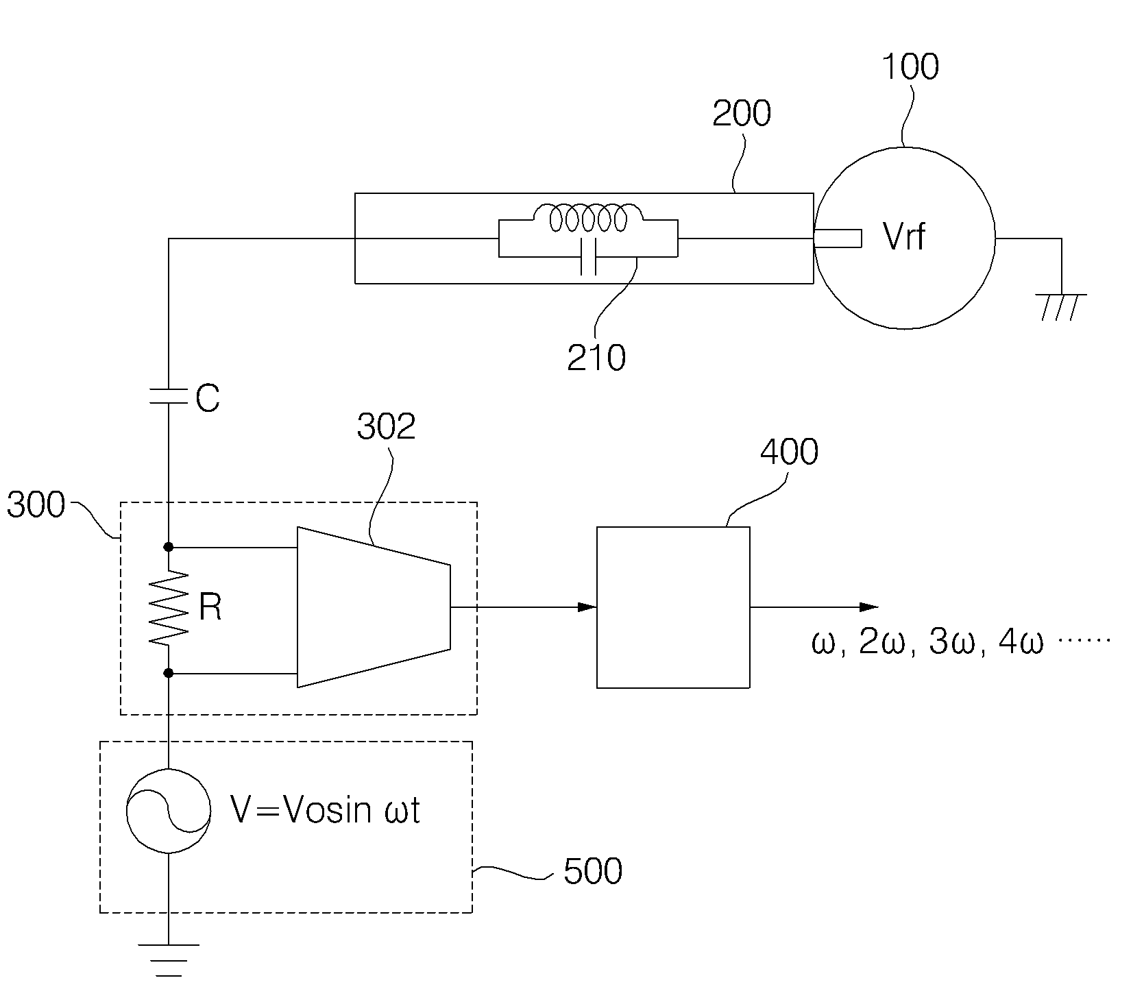
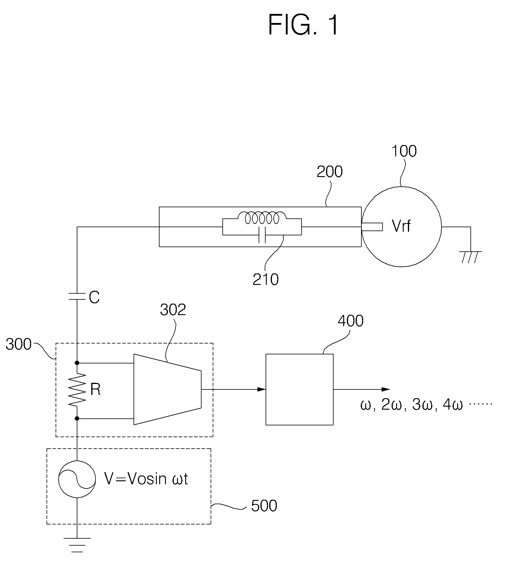
Image

Examples
experimental example 1
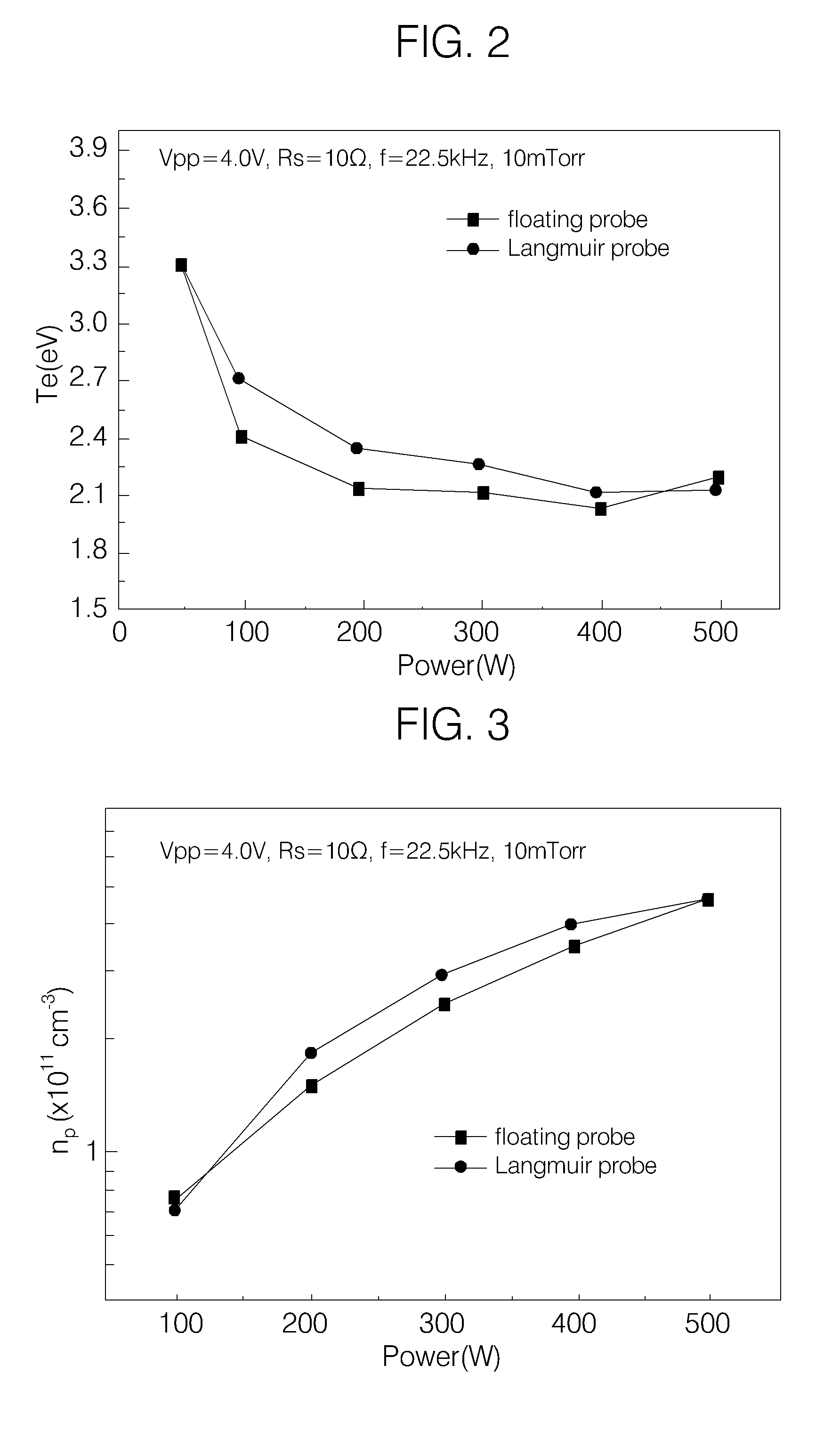
[0098]FIG. 2 and FIG. 3 are graphs comparing electron temperatures and ion densities respectively measured using a floating probe according to the present invention and the well-known single Langmuir probe in an argon gas atmosphere at a pressure of 10 mTorr.
[0099]As shown in the graphs, the results measured using the floating probe according to the present invention correspond to the results measured using the Langmuir probe in the input power region, accordingly this shows that the results measured using the floating probe according to the present invention are very reliable.
experimental example 2
[0100]Also, FIG. 4 and FIG. 5 are graphs comparing electron temperatures and ion densities respectively measured using the floating probe according to the present invention and the well-known single Langmuir probe in an argon gas atmosphere at a pressure of 20 mTorr.
[0101]As shown in the graphs, the results measured using the floating probe according to the present invention also correspond to the results measured using the Langmuir probe in the input power region, accordingly this also shows that the results measured using the floating probe according to the present invention are very reliable.
experimental example 3
[0102]FIG. 6 and FIG. 7 are graphs showing results measured using the well-known Langmuir probe and the floating probe according to the present invention respectively after mixing an argon gas and a CF4 gas used in actual semiconductor process in the ratio of 8:2.
[0103]Referring to FIG. 6, as the Langmuir probe measures the conduction current of an ion or an electron directly, when an insulation layer is deposited on the surface of the Langmuir probe through the CF4 plasma, the Langmuir probe cannot measure. Therefore, the Langmuir probe may not be used for plasma diagnostic in a substantial mixture gas(refer to the red graph in FIG. 6).
[0104]On the other hand, Referring FIG. 7, as the floating probe according to the present invention measures AC current, though the insulation layer is deposited to some degree on the surface of the floating probe through the CF4 plasma, the insulation layer may not significantly affect the measurement result of the ion density or electron temperatur...
PUM
| Property | Measurement | Unit |
|---|---|---|
| pressure | aaaaa | aaaaa |
| pressure | aaaaa | aaaaa |
| frequency | aaaaa | aaaaa |
Abstract
Description
Claims
Application Information
 - R&D
- Intellectual Property
- Life Sciences
- Materials
- Tech Scout
- Unparalleled Data Quality
- Higher Quality Content
- 60% Fewer Hallucinations
Browse by: Latest US Patents, China's latest patents, Technical Efficacy Thesaurus, Application Domain, Technology Topic, Popular Technical Reports.
© 2025 PatSnap. All rights reserved.Legal|Privacy policy|Modern Slavery Act Transparency Statement|Sitemap|About US| Contact US: help@patsnap.com