
Non-lethal projectile with flowable payload

a payload and non-lethal technology, applied in the field of non-lethal projectiles, to achieve the effect of reducing the impact pressure, reducing the initial velocity of the projectile, and improving the maximum effective range and precision

Inactive Publication Date: 2010-04-06
CRONEMBERGER PEDRO DE OLIVEIRA
View PDF9 Cites 8 Cited by
  • Summary
  • Abstract
  • Description
  • Claims
  • Application Information

AI Technical Summary

Benefits of technology

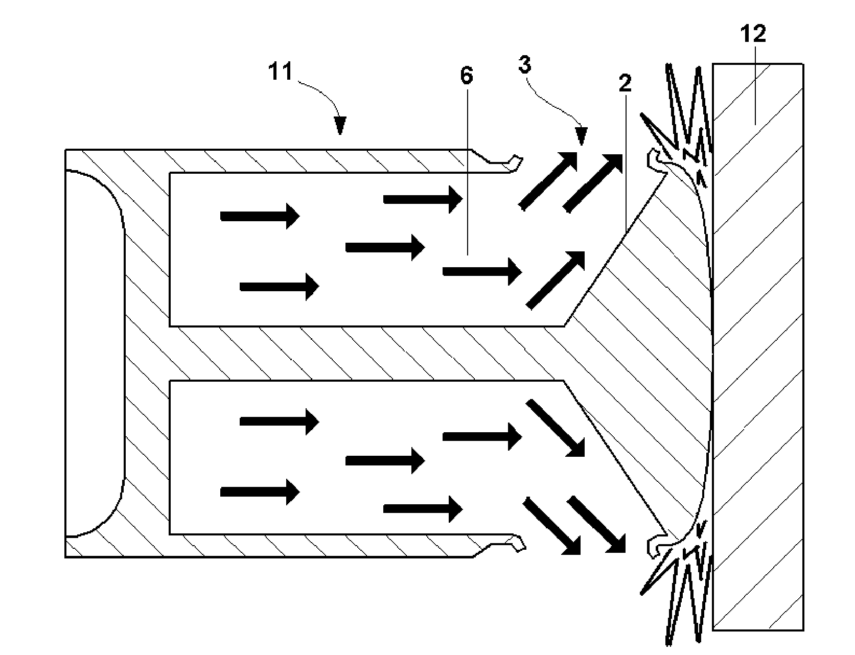
[0014]When a projectile filled with a flowable payload hits a target, the payload is strongly pushed in the direction of projectile's point by action of inertia. This effect creates in the payload an instantaneous pressure distribution that has its maximum value toward projectile's point. In the present invention, the capsular area closer to the point is specially weakened. This weakened area placed exactly where the pressure has a maximum value makes the rupturing faster, avoiding the projectile to impart too much energy to the target before the capsule collapses.
[0017]First, this flow represents a deflection of momentum. It means that the projectile's payload momentum will be smoothly deflected radially, by a hydrodynamic shaped structure. The consequence of this momentum deflection is a less concentrated impact energy and a lower pressure over target's surface.
[0018]Second, this forcing against the weakened area makes the complete rupture easier. Together with the inertial effect, this directional forcing of the flow helps the projectile's point not to pressure the target's surface too much long before the weakened area collapses.
[0019]This reduction in the impact pressure allows the projectile to hit the target at higher velocities, causing acceptable damages. This way, it is possible to impart a higher initial velocity to the projectile, obtaining a higher maximum effective range and precision.
[0021]The use a high density flowable payload brings two major advantages: first, the total weight of the projectile approximates to the weight of a lead-core common projectile, allowing the projectile to have range and precision performances closer to lethal ammunitions. Second, this high density increases the payload's portion in the projectile weight distribution, turning the impact of the projectile more similar to the impact of a whole fluid mass.

Problems solved by technology

a) keep the projectile's integrity during the feeding and firing procedures;
b) be stable in flight, hitting nose first;
c) rupture upon impact, causing controlled damage to the target.

Method used


Image

  • Non-lethal projectile with flowable payload
  • Non-lethal projectile with flowable payload
  • Non-lethal projectile with flowable payload

Examples


Embodiment Construction

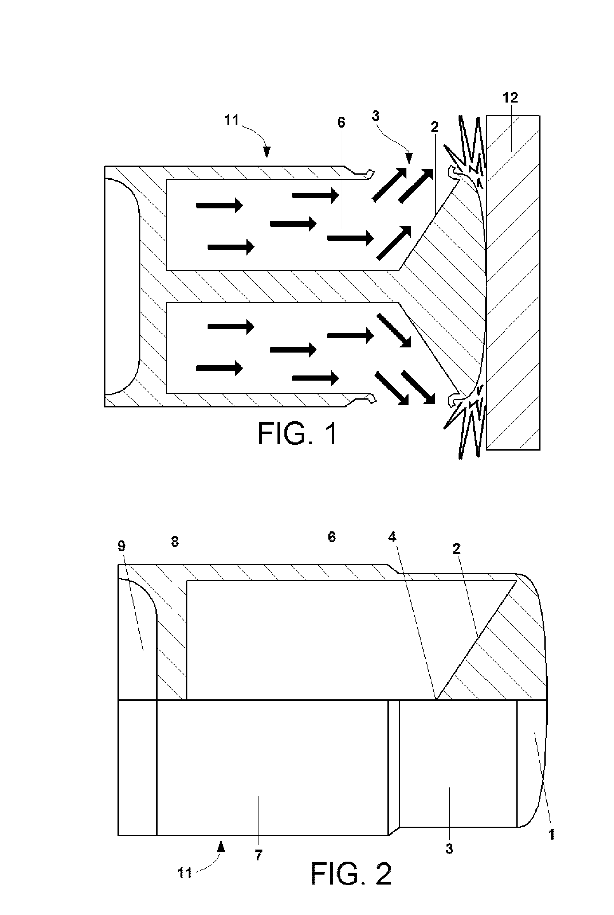
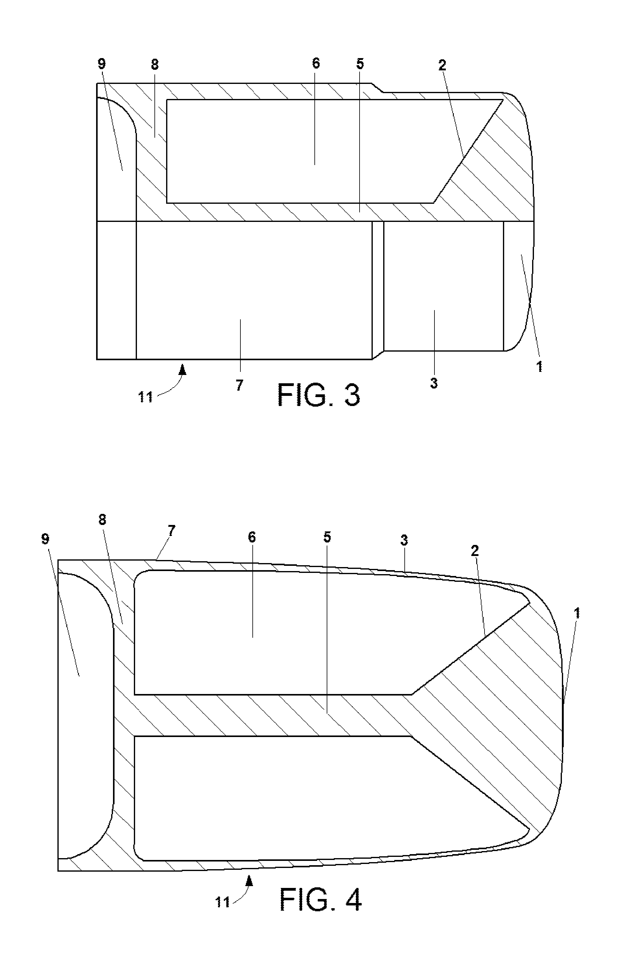
[0038]As can be seen in FIG. 1, the projectile of this invention consists of a solid capsule (11) that is filled by a flowable payload (6). When the projectile hits a target (12), the payload (6) is pushed forward by action of inertia. The inertial effect creates a pressure gradient with maximum value close to the point (1). By the effect of this pressure, the weakened area (3) ruptures, allowing the payload (6) to be radially spread out. A hydrodynamic structure (2) forces the radial flow of the payload (6), from the center to the periphery, against the weakened area (3).

[0039]The solid capsule (11) is made to be light weighted, using light structural materials, such as engineering plastics or aluminum alloys. Polyamides have been shown applicable. In opposite, the flowable payload (6) is selected to have the greater density, and consequently the greater total weight, as possible. However, this desirable high density shall not cause an elevation in viscosity that could harm the flo...


PUM


Abstract

A non-lethal projectile consisting of a solid capsule filled with a flowable payload. The solid capsule comprises a weakened area that ruptures upon impact with a target. The solid capsule also comprises an internal hydrodynamic structure. At the moment of impact, the internal hydrodynamic structure forces the radial movement of the flowable payload, from the center to the periphery, against the weakened area of the solid capsule, facilitating the rupture and reducing the pressure of projectile's point over target's surface.

Description

BACKGROUND OF THE INVENTION[0001]The present invention relates to non-lethal projectiles that are filled with a flowable payload and designed to rupture upon impact with a target.[0002]Non-lethal projectiles containing a flowable payload are basically used in three fields: the field of non-lethal kinetic energy projectiles, the field of non-lethal chemical projectiles and the field of marker projectiles.[0003]Some projectile geometries were already proposed, trying to overcome simultaneously the following major problems:[0004]a) keep the projectile's integrity during the feeding and firing procedures;[0005]b) be stable in flight, hitting nose first;[0006]c) rupture upon impact, causing controlled damage to the target.[0007]In the field of non-lethal chemical projectiles, the U.S. Pat. No. 7,194,960 B2 describes a frangible projectile that ruptures upon impact, omnidirectionally dispersing an inhibiting powder payload. The impact creates a cloud of inhibiting powder substance over th...

Claims


Application Information

Patent Timeline
Patent Type & Authority Patents(United States)
IPC IPC(8): F42B10/00
CPCF42B5/145F42B12/46F42B12/40
Inventor CRONEMBERGER, PEDRO DE OLIVEIRA
Owner CRONEMBERGER PEDRO DE OLIVEIRA
Learn More