
Shift register and shift register unit for diminishing clock coupling effect

a shift register and shift register technology, applied in the field of shift register and shift register unit, can solve problems such as poor pull-down performance, and achieve the effect of optimizing the waveform output of the shift register and reducing the clock coupling

Active Publication Date: 2010-03-30
OPTRONIC SCI LLC
View PDF10 Cites 37 Cited by
  • Summary
  • Abstract
  • Description
  • Claims
  • Application Information

AI Technical Summary

Benefits of technology

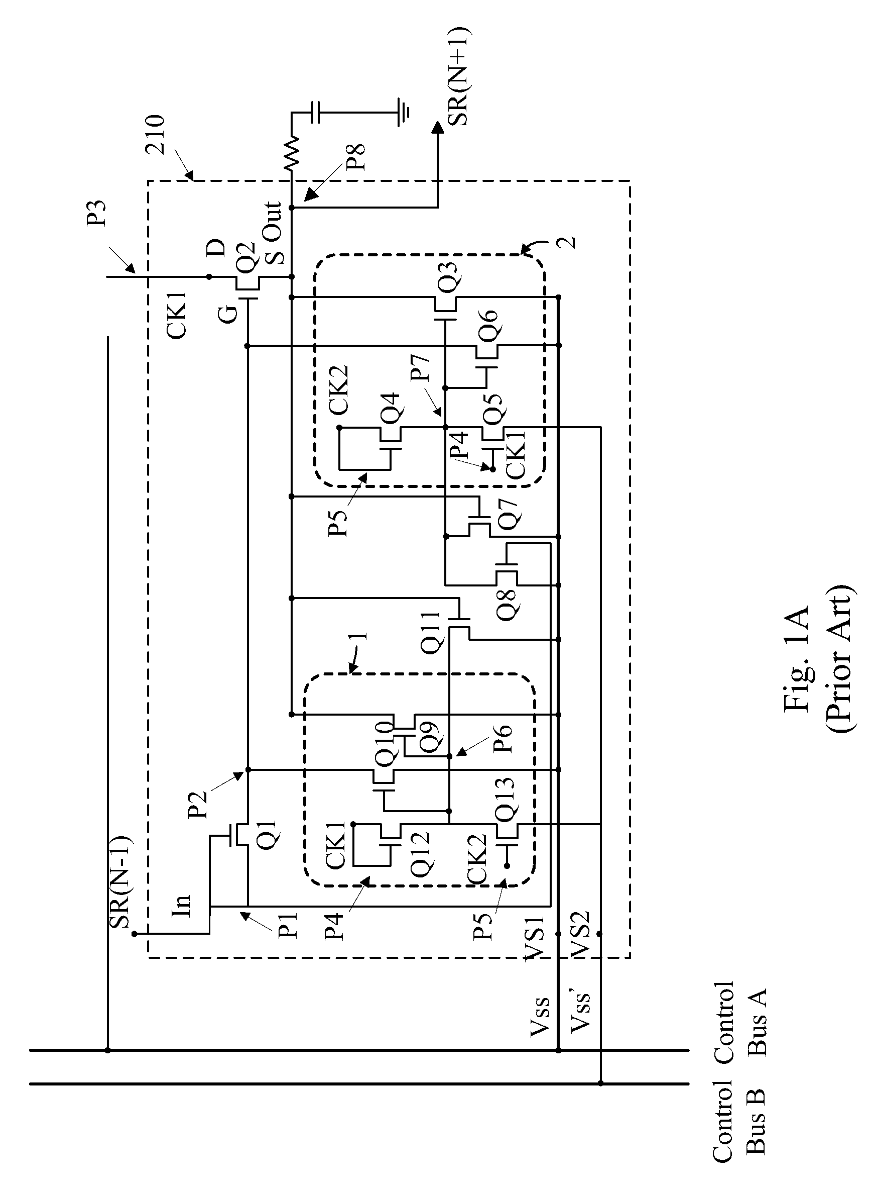
[0008]To resolve the abovementioned drawbacks, a primary object of the present invention is to provide a shift register and a shift register unit used for diminishing clock coupling effect, which employ other periodic signals for driving a pull-down module and thereby provide the pull-down module with a capability of sufficiently resisting the clock coupling effect occurring in clock signal, so as to optimize waveform output of the shift register.
[0014]In another embodiment, each of the pull-down driving modules of the shift register unit can be changed to connect with a second source voltage having a level lower than that of the first source voltage, and thereby timely turn off the corresponding pull-down modules.
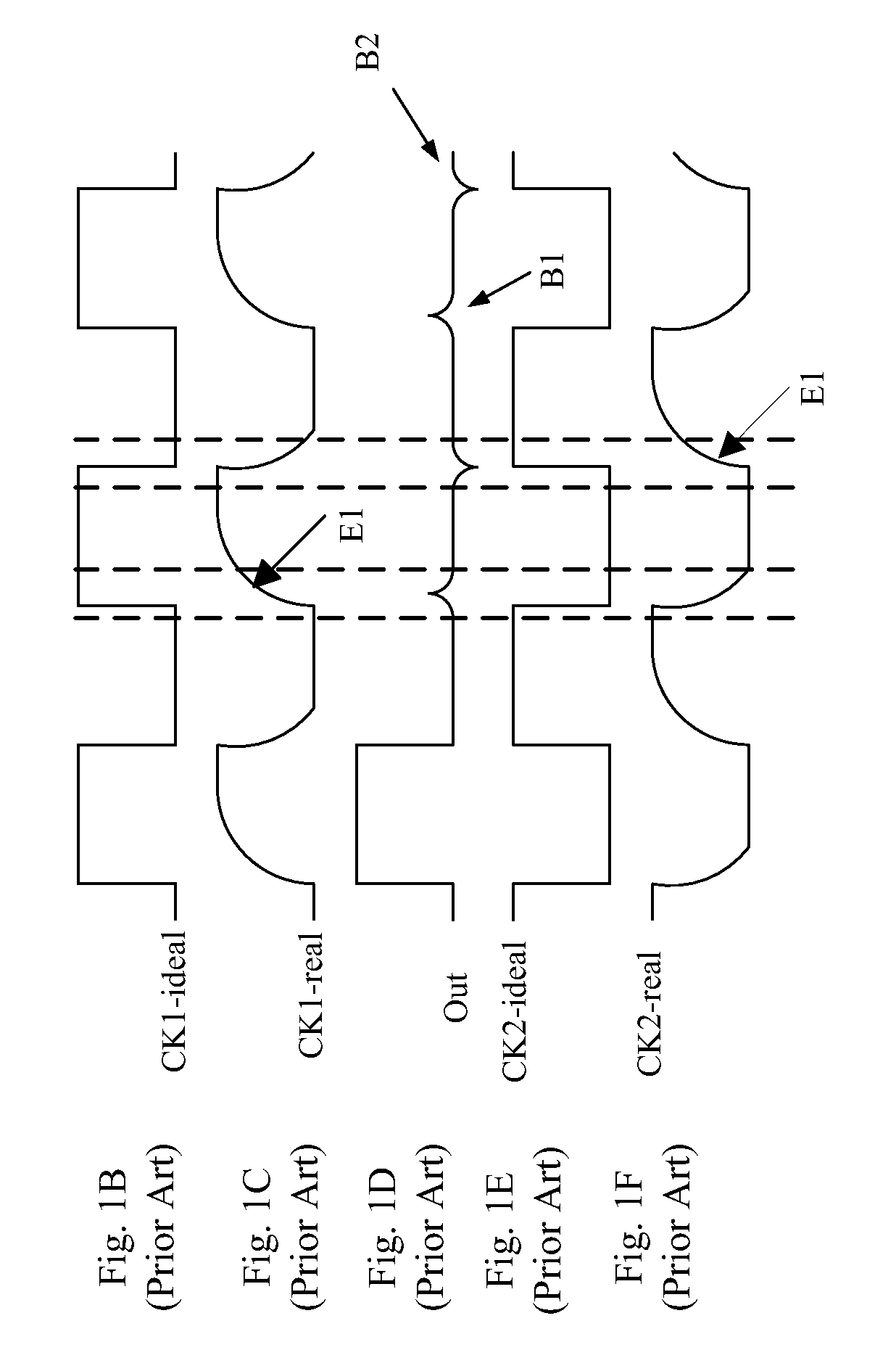
[0015]In another embodiment, before the first clock signal transits from a low level to a high level, a capacitor is used to pre-maintain the second periodic signal at the high level which can turn on the pull-down module, and thereby can resist the coupling effect.

Problems solved by technology

Simultaneously, with involvement of driving the pull-down modules 1 and 2 in delays by the first clock signal (CK1), a signal level of either an output node (P8) or an input node (P2) of a pull-up module containing the pull-up transistor of Q2 also would not be timely pulled down and therefore provides a poor pull-down performance.

Method used


Image

  • Shift register and shift register unit for diminishing clock coupling effect
  • Shift register and shift register unit for diminishing clock coupling effect
  • Shift register and shift register unit for diminishing clock coupling effect

Examples


second embodiment

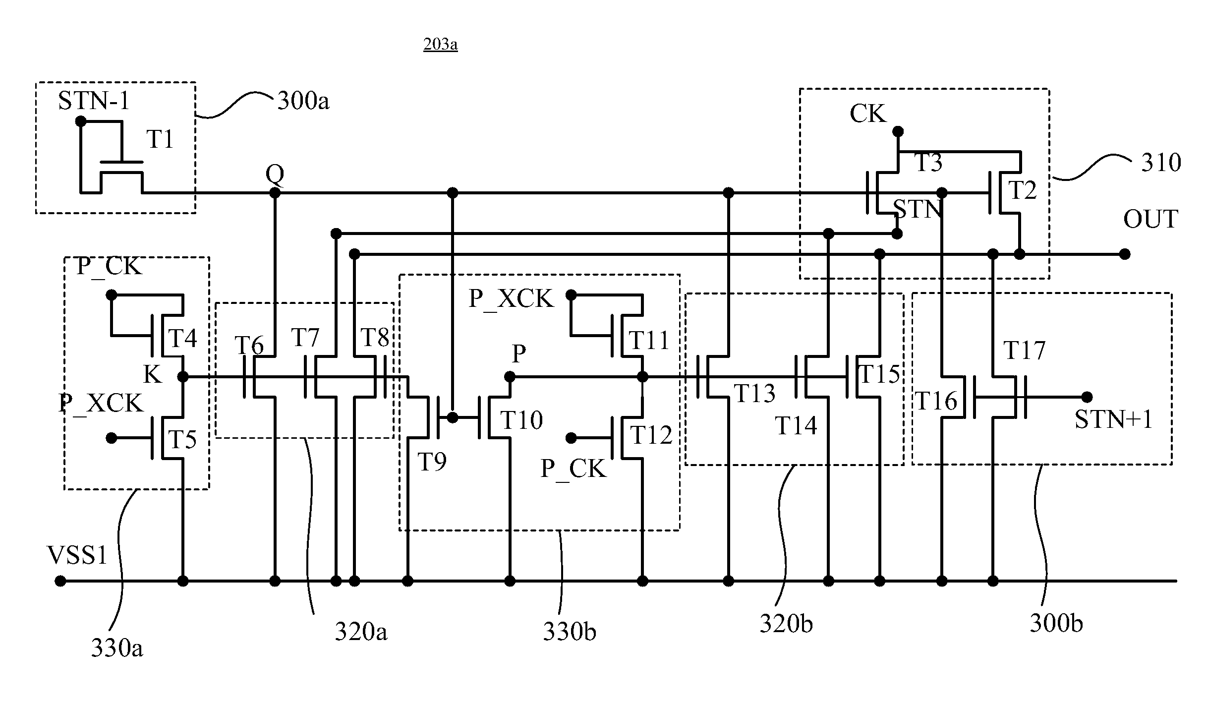
[0047]Further referring to FIG. 6A to FIG. 6H, which illustrate various signal waveforms of the shift register unit 203b according to the present invention, which depict the lowest level of each of the first clock signal (CKO), the second clock signal (XCKO) and a setting signal (STN−1) generated from the previous stage shift register unit 203b and an input signal of the input node (Q) of the shift register unit 203b is the same as the level of the first source voltage (VSS1), but the lowest level of each of the first periodic signal (CKE), the second periodic signal (XCKE), the signal of the first input node (K) of the first pull-down module 320a and the signal of the second input node (P) of the second pull-down module 320b is the same as the level of the second source voltage (VSS2).

third embodiment

[0048]Further referring to illustration of FIG. 3C, a shift register unit 203c according to a third prefer embodiment of the present invention is introduced herein. As the same as shown in FIG. 2, the shift register unit 203c can be one of the odd-stage cascaded shift register unit (e.g. GOA1, GOA3, GOA5 . . . GOAN) and the even-stage cascaded shift register units (e.g. GOA2, GOA4, GOA6 . . . GOAN+1). The shift register unit 203c of the third embodiment is designed only for connecting the first signal (CK), the second signal (XCK) and the fourth signal (P_XCK), and primarily comprises a first pull-up driving module 300a, a second pull-up driving module 300b, a pull-up module 310, a pull-down module 320, and a pull-down driving module 330.

[0049]The first pull-up driving module 300a of the shift register unit 203c comprises a first transistor (T1) having a drain and a gate both jointed to a pulse signal, such as a setting signal (STN−1) generated from the previous stage shift register...


PUM


Abstract

A shift register and a shift register unit for diminishing clock coupling effect are introduced herein. Each stage shift register unit includes at least one pull-up driving module, a pull-up module, at least one pull-down module and a pull-down driving module. Before a waveform of either a first clock signal or a second clock signal employed by the pull-up module transits into a rising edge, the pull-down driving module employs a first periodic signal to turn on the pull-down module in advance for a specific period, and / or before the waveform of the first or second clock signal employed by the pull-up module transits into a falling edge, the pull-down driving module employs a second periodic signal to turn off the pull-down module in advance for a specific period. Accordingly, the pull-down module can gain a sufficient capability against the clock coupling effect so as to optimize the waveform outputted from the shift register unit.

Description

BACKGROUND OF THE INVENTION[0001]1. Field of the Invention[0002]The present invention relates to a shift register and a shift register unit, and more particularly to a shift register and a shift register unit used for diminishing clock coupling effect.[0003]2. Description of the Prior Art[0004]Conventional liquid crystal display (LCD) utilizes a set of driving circuits for controlling gray signal outputs of a plurality of pixel units located in a LCD panel. The driving circuits further include a gate driver electrically connected with transverse scan lines (or gate lines) in turn each for outputting a gate pulse signal to each corresponding pixel unit, and a source driver electrically connected with longitudinal data lines (or source lines) each for transmitting a data signal to each corresponding pixel unit 20 separately. Each of the intersections between the transverse scan lines and longitudinal data lines is electrically connected with two terminals of an active component (such ...

Claims


Application Information

Patent Timeline
Patent Type & Authority Patents(United States)
IPC IPC(8): G11C19/00
CPCG11C19/28G09G3/3677
Inventor TSAI, TSUNG-TINGLAI, MING-SHENGCHEN, YUNG-CHIHLIU, PO-YUAN
Owner OPTRONIC SCI LLC
Learn More