
Method for providing enhanced stability of a vehicle with a deflated tire

a technology of deflated tires and enhanced stability, which is applied in the direction of vehicle tyre testing, braking systems, braking components, etc., can solve the problems of inadequate lateral force to maintain the desired turning radius, vehicle yaw or spin, and inability to support the same forces of deflated tires, so as to reduce the current magnitude of brake pressure and enhance the stability of the motor vehicle

Active Publication Date: 2010-03-16
KELSEY HAYES CO
View PDF39 Cites 15 Cited by
  • Summary
  • Abstract
  • Description
  • Claims
  • Application Information

AI Technical Summary

Benefits of technology

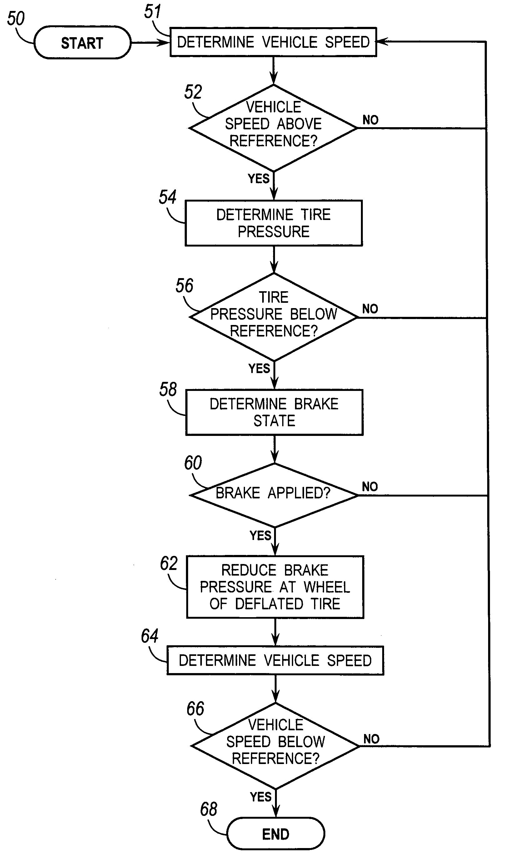
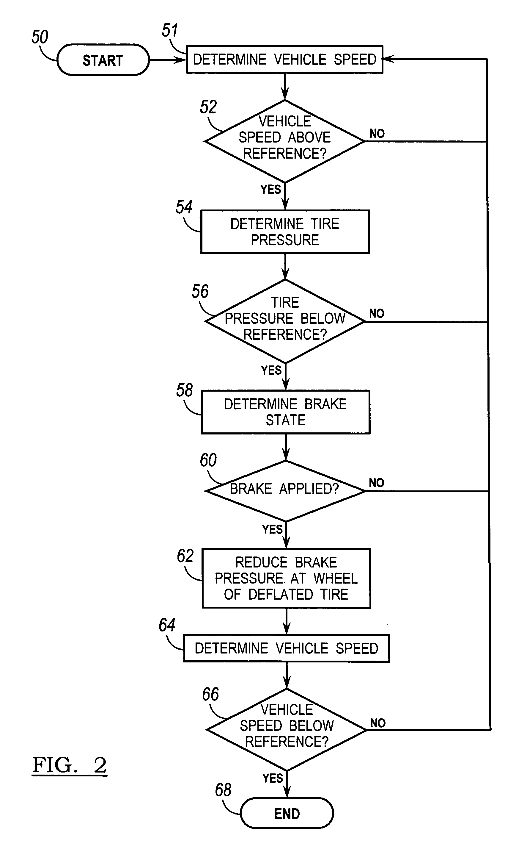
[0008]This invention relates to a method for enhancing stability of a motor vehicle equipped with pneumatic tires and a hydraulically actuated wheel brake system. The method includes determining whether any tire on the vehicle is deflated, determining the current magnitude of brake pressure at the wheel of the deflated tire when the brakes are applied, and reducing the current magnitude of brake pressure at the wheel of the deflated tire. Preferably, brake pressure at both the left and right wheels at the front or rear axles where the deflated tire is located is reduced.

Problems solved by technology

In the event of a rapid tire deflation or blowout in a motor vehicle, the deflated tire is unable to support the same forces and moments as the inflated tire on the opposite side of the same axle.
First, the longitudinal force between the road and the tire created by a given braking torque can be lower for a deflated tire than an inflated tire because a delay in transmitting brake torque to the road is increased at the deflated tire.
The result, in either case, is a difference in magnitude of longitudinal forces at the left and right wheels of a given axle, which induces a yaw moment on the vehicle and tends to cause the vehicle to yaw or spin.
Therefore, if the vehicle is turning, there may be inadequate lateral force to maintain the desired turning radius.
With a front tire, the result is understeer, which induces the vehicle to plow out of the turn, while with a rear tire, the result is oversteer, which induces vehicle yawing or spinning about a vertical axis.
Application of braking forces to a tire reduces its lateral force support capability, so applying braking force to a deflated tire further reduces its capability.
The second factor causes inadequate lateral force capability to control the spin which then may increase out of control.

Method used


Image

  • Method for providing enhanced stability of a vehicle with a deflated tire
  • Method for providing enhanced stability of a vehicle with a deflated tire
  • Method for providing enhanced stability of a vehicle with a deflated tire

Examples


Embodiment Construction

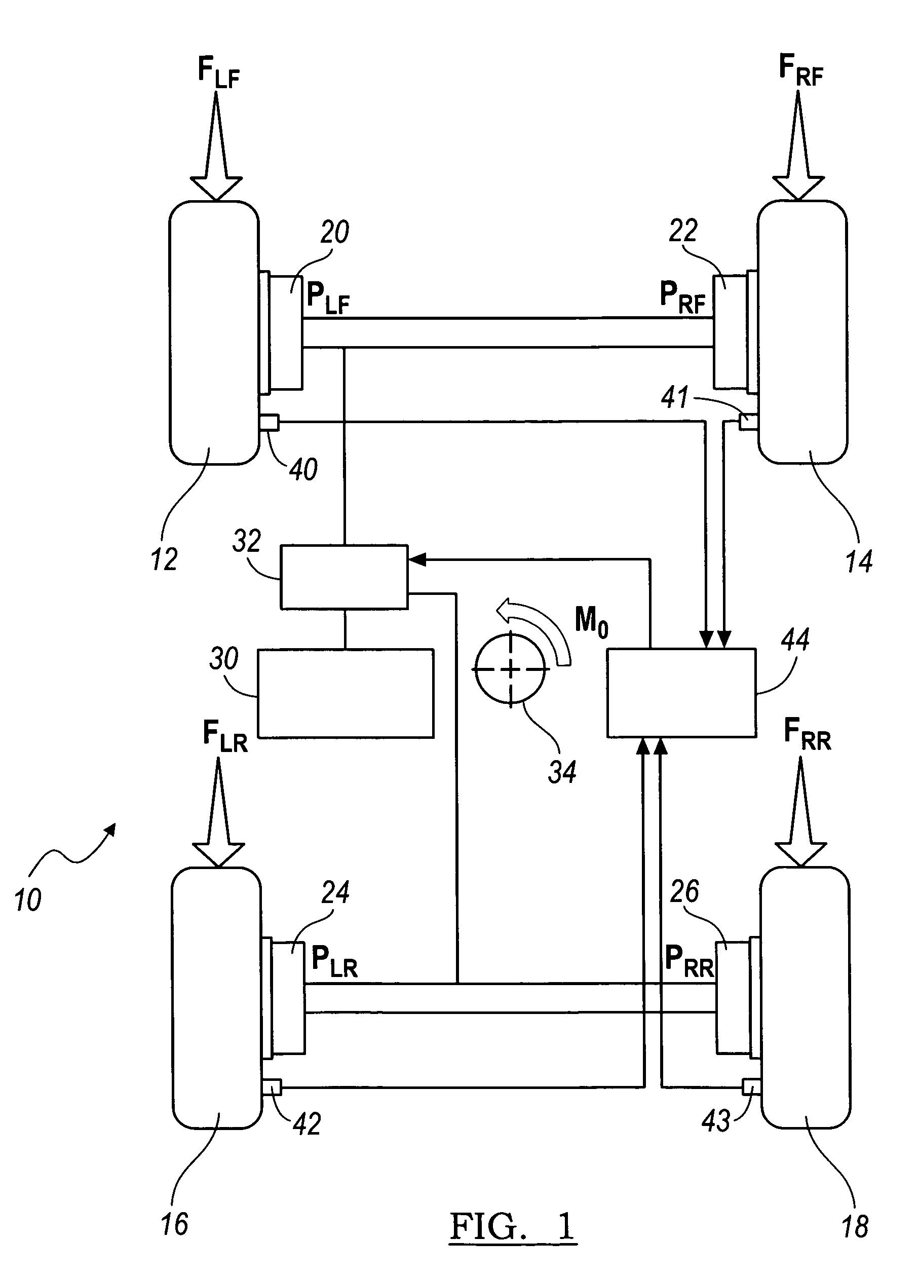
[0017]Referring now to the drawings, there is illustrated in FIG. 1 a motor vehicle 10 that is supported on front wheels, each fitted with a tire 12, 14 and rear wheels, each fitted with a tire 16, 18. The rotational speed of the front wheels is controlled by front brakes 20, 22; the rotational speed of the rear wheels is controlled by rear brakes 24, 26. A source of brake pressure 30 is hydraulically connected through an anti-lock brake system (ABS) controller or vehicle stability control (VSC) modulator 32 to the front brakes, to which brake pressures PLF and PRF are applied and to the rear brakes, to which brake pressures PLR and PRR are applied. In the following description, the front wheels 12 and 14 are sometimes referred to as the front axle; while the rear wheels 16 and 18 are sometimes referred to as the rear axle.

[0018]Under normal forward driving conditions when the front brakes are applied, the brake pressure source 30 delivers brake pressure that is approximately equal ...


PUM


Abstract

In a motor vehicle equipped with pneumatic tires and a hydraulically actuated wheel brake system, a method for enhancing stability of the vehicle by determining whether any tire on the vehicle is deflated, determining the current magnitude of brake pressure at the wheel of the deflated tire when the brakes are applied, and reducing the current magnitude of brake pressure at the wheel of the deflated tire.

Description

CROSS-REFERENCE TO RELATED APPLICATIONS[0001]Not ApplicableBACKGROUND OF THE INVENTION[0002]This invention relates in general to a control method for enhancing stability of a vehicle by adjusting brake pressure following deflation of a tire to a lower pressure.[0003]In the event of a rapid tire deflation or blowout in a motor vehicle, the deflated tire is unable to support the same forces and moments as the inflated tire on the opposite side of the same axle.[0004]At least two factors are important in this respect. First, the longitudinal force between the road and the tire created by a given braking torque can be lower for a deflated tire than an inflated tire because a delay in transmitting brake torque to the road is increased at the deflated tire. Therefore, there is a brief period during which the inflated tire is creating a larger force. Additionally, the maximum coefficient of friction between the tire and road may be decreased in a deflated tire, thereby reducing the maximum...

Claims


Application Information

Patent Timeline
Patent Type & Authority Patents(United States)
IPC IPC(8): G01M17/02
CPCB60T8/1725B60T8/1755B60T8/17616B60T8/885G01M17/06B60T2240/03B60T2270/402
Inventor BARTOL, MARK
Owner KELSEY HAYES CO
Learn More