
Polymorphic automatic test systems and methods

a technology of applied in the field of polymorphic automatic test system and method, can solve the problems of over-utilization of unused resources for other tasks, all resources not needed to test the particular device under test remain idle, and the cost of writing these job programs exceeds the capital cost of automatic test equipment, so as to increase the utilization of tester resources and increase the productivity of our novel testers

Inactive Publication Date: 2010-03-02
PRACTICAL ENG
View PDF44 Cites 10 Cited by
  • Summary
  • Abstract
  • Description
  • Claims
  • Application Information

AI Technical Summary

Benefits of technology

"The present invention is an automatic test system for testing analog and mixed signal semiconductor devices. The system has a unique architecture that allows for the creation of virtual composite instruments that mimic existing instruments and are dynamically allocated to run multiple job programs simultaneously. The system includes a software layer that maintains a list of available resources and their current state, and a hardware layer that includes at least two resource instrument components associated with at least two test elements. The system can be adapted to operate as a server and interact with multiple clients concurrently or virtually simultaneously. The virtual composite instruments include a composite instrument component with at least two resource instrument components associated with at least two test elements and a composite instrument template for combining the components to form an interactive object. The system also includes a dynamic resource allocation component that allocates and de-allocates one or more complete components or sub-components of physical instruments to facilitate the running of multiple test job programs dynamically. The system combines several metering, source, and control resources together in software to create a composite instrument that can use different existing languages and does not need one common language."

Problems solved by technology

This means that all resources not needed to test the particular device under test remain idle for the duration of the test program.
Importantly, traditional analog / mixed signal automatic test equipment software architectures do not allow the use of the unused resources for any other tasks during testing.
Users write job programs for this automatic test equipment and commonly the cost of writing these job programs exceeds the capital cost of the automatic test equipment.
In order to change to another brand of automatic test equipment or to a newer version of the current system, it is frequently necessary to port these programs to a new proprietary language at great expense.
They do not allow for the running of the tester remotely.
Large losses of productivity can sometimes be traced to the suiting up process prior to entering a clean room environment.
Since tester performance is frequently an interpretation of test results from specialized job programs, communication can be difficult across language barriers.
There are several disadvantages with this architecture that allocates resources to the test job programs at the initialization time and releases them only at the end of the program.
This architecture is again relatively inefficient.
However, this architecture is relatively inflexible since it cannot flexibly replace the connected meter with a meter having a higher accuracy (such as the precision calibration meter of the instrument primarily used for test calibration).

Method used


Image

  • Polymorphic automatic test systems and methods
  • Polymorphic automatic test systems and methods
  • Polymorphic automatic test systems and methods

Examples


Embodiment Construction

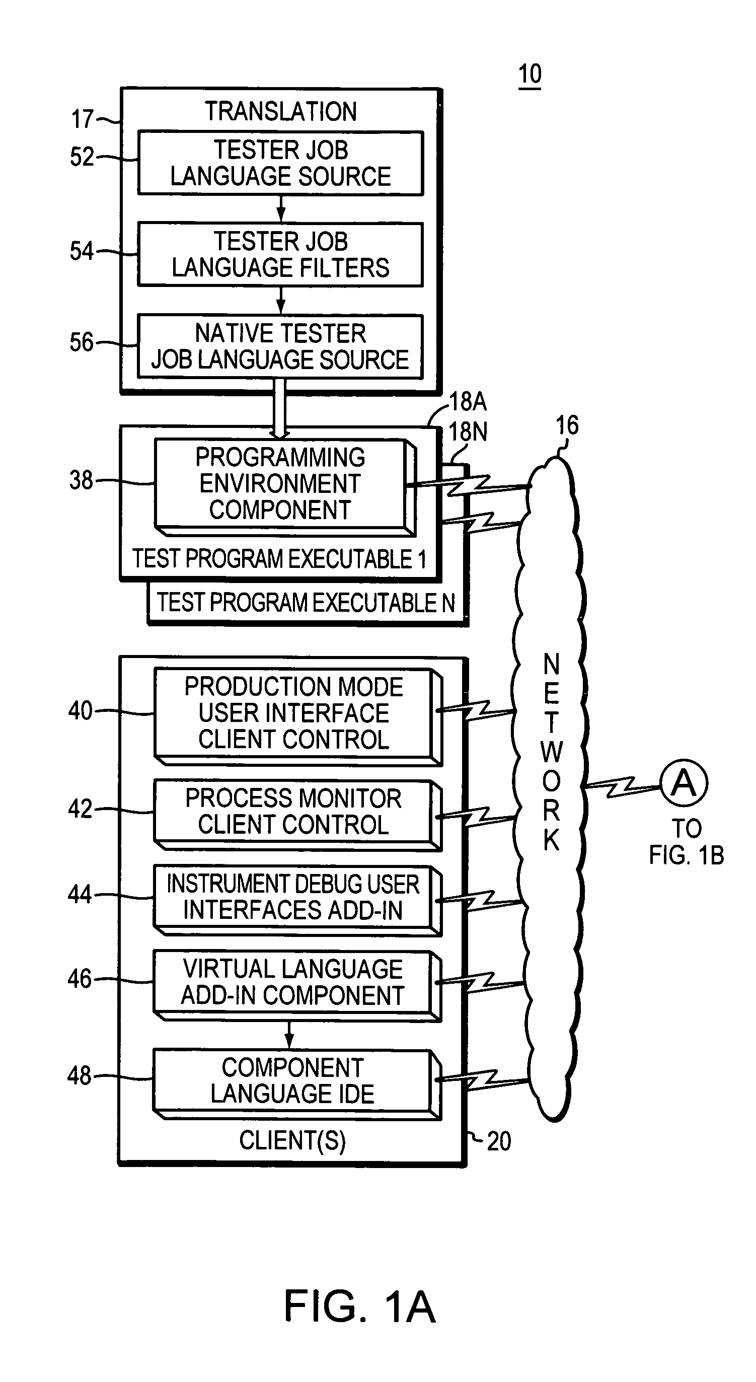
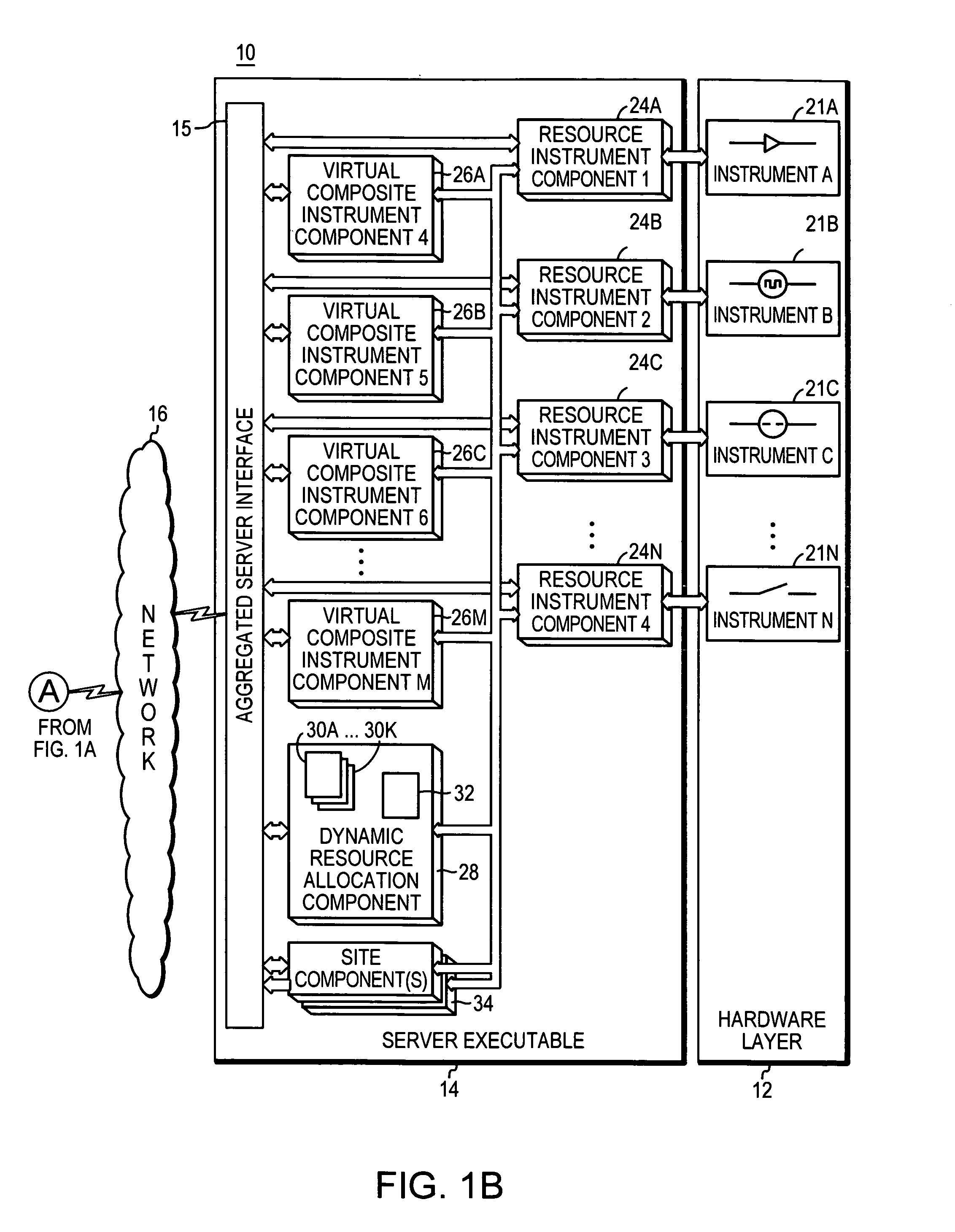
[0051]FIGS. 1A and 1B are high level block diagrams of a polymorphic automatic test equipment system 10, which illustrate a hardware layer 12 and a software architecture including server executable 14 (FIG. 1B) and external job executables 18A through 18N (FIG. 1A). Hardware layer 12 includes several hardware resources 21A, 21B . . . 21N, generally considered at a low level of capability. Polymorphic automatic test equipment system 10 uses any of the known and publicly available computer hardware systems.

[0052]For example, hardware layer 12 may include one or a group of each of the following hardware elements: A control bit, a voltmeter, an amp meter, a current source, a digital drive channel, a digital receive channel, a clock, a time measurement meter, an AC source, a digitizer, an RF source, an RF detector, an RF meter, relays, and / or optical elements including a laser diode, an LED, or other sources of electromagnetic radiation, and a photodiode, a photoresistor or other detecto...


PUM

PropertyMeasurementUnit
frequencyaaaaaaaaaa
voltageaaaaaaaaaa
voltageaaaaaaaaaa

Abstract

An Analog / mixed signal automatic test system includes a software architecture that creates a virtual composite instruments through novel software dynamic allocation of low level resources. These virtual composite instruments provide backwards and forwards compatibility to a variety of automatic test equipment, known or available on the market. The virtual composite instruments are free from the normal constraints imposed by hardware implementations. Creation of the virtual composite instruments allows a single piece of automatic test equipment system to emulate many implementations of automatic test equipment, providing higher utilization, and therefore a lower cost test solution for device manufacturers. The test instruments are preferably object controls and are preferably instantiated and controlled by the test system server. This allows multiple users to control the tester simultaneously across, for example, the Internet.

Description

[0001]This application claims priority from U.S. Provisional Application 60 / 524,231, filed on Nov. 20, 2003, which is incorporated by reference.[0002]The invention relates generally to automatic test equipment, and more particularly to analog / mixed signal automatic test systems.BACKGROUND OF THE INVENTION[0003]Automatic test equipment provides the ability for semiconductor device manufacturers to test semiconductor devices. By testing every device, the manufacturer can reject or accept the device and separate those rejected prior to them entering commerce.[0004]Testing a semiconductor device typically involves the application of known signals to specific pins while measuring the output reaction of the device to those input signals. The output signals are then compared to the expected reactions and to determine whether the device under test (DUT) matches specified parametric limits.[0005]Analog / mixed signal automatic test equipment architectures have traditionally been designed with ...

Claims


Application Information

Patent Timeline
Patent Type & Authority Patents(United States)
IPC IPC(8): G01R31/28G01L15/00G06F11/30G01M99/00G06F11/00G08C25/00H01LH03M13/00H04L1/00
CPCG01R31/2834
Inventor LUFF, EDWIN F.PLATSIDAKIS, MICHAEL
Owner PRACTICAL ENG
Learn More