
Low power signal transmission

a low-power signal and transmission technology, applied in the direction of transmission, ear treatment, head electrodes, etc., can solve the problems of over-whelming percentage of total power consumption, negligible power consumption of processing in the baseband, and large threshold voltage of diode rectifiers, so as to eliminate low-frequency spectral components

Active Publication Date: 2010-02-02
MED EL ELEKTROMEDIZINISCHE GERAETE GMBH
View PDF21 Cites 10 Cited by
  • Summary
  • Abstract
  • Description
  • Claims
  • Application Information

AI Technical Summary

Benefits of technology

The patent describes a method and system for a low-power implant system that uses ultra wideband pulses for communication. The implant is capable of communicating with a device outside the person via the transmission of these pulses. The system can have unidirectional or bidirectional communication, and the implant can provide electrical stimulation based on the received acoustic signal. The device can include a transmitter and a receiver, and the receiver can include a time-gated amplifier for synchronizing with the pulses. The system can also include a first external signal processor for providing information to a hearing aid or an implant, and a second external signal processor for processing information in the other ear. The ultra wideband pulses have a duty cycle of 1 / 1000 or less, a time duration of between 0.5 ns and 10 ns, and a pulse repetition time between 5 and 100 μs.

Problems solved by technology

Note that the overwhelming percentage of the total power consumption results from the RF components at the transmitting and / or receiving end.
The power consumption of processing in the baseband is negligible due to the low speed power product of modern CMOS technology and the comparative low frequencies of the baseband.
However, the threshold voltage of the diode rectifier may be too large, even when using backward diodes for demodulation.
Another very low power receiver is the superregenerative receiver, which does not have sufficient bandwidth for transmission of coded speech signals.
However, in each of these cases the power consumption of the RF amplification is non-negligible.
However, total power consumption may be too large in any event.

Method used


Image

  • Low power signal transmission
  • Low power signal transmission
  • Low power signal transmission

Examples


Embodiment Construction

[0028]In illustrative embodiments of the invention, a system and method for low power signal transmission between, for example, parts of a hearing system, is presented. The low power signal transmission is achieved by transmitting very short ultra wideband (UWB) pulses. In various embodiments, the transmitted UWB signals are representative of signals having a bandwidth not exceeding 1 or 2 MHz. The UWB pulses can thus be transmitted at a very small duty cycle, resulting in very low transmitter power consumption. Additional power savings are realized at the receiver by using passive receivers or gated receivers which are synchronized to the incoming UWB pulses. Details of illustrative embodiments are discussed below.

[0029]Ultra Wideband (UWB) technology is a relatively new communication technology that is fundamentally different from communication using modulated methodologies. See for example, U.S. Pat. No. 6,031,862, entitled “Ultra-wideband Communication System and Method,” which ...


PUM


Abstract

A low-power implant system. The system includes an implant for implantation into a person, such as a cochlear implant or a middle ear implant. The implant is capable of communicating with a device via transmission of ultra wideband pulses. The device may be adapted to be worn external to the person, or may be a second implant. So as to conserve battery power, the transmitted ultra wideband pulses may have a low duty cycle of approximately 1 / 1000 or less. Power savings may also be realized by using time-gating amplifiers in the implant and / or device receiver.

Description

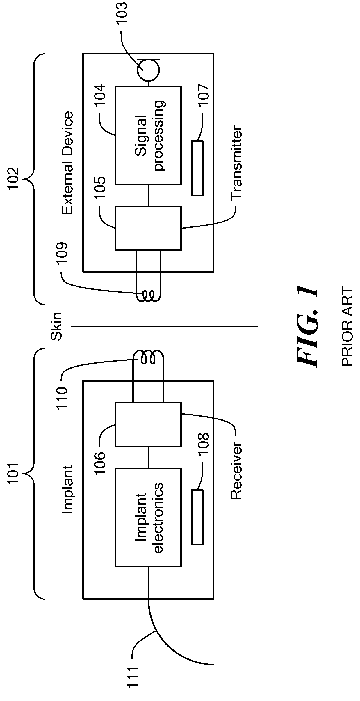
PRIORITY[0001]This application claims priority from U.S. Provisional Application No. 60 / 384,948, filed May 31, 2002, entitled “Low Power Signal Transmission Over Short Distances”, the disclosure of which is incorporated herein by reference.TECHNICAL FIELD[0002]The present invention relates to low power signal transmission over short distances, which may be used, for example, in implanted devices such as a cochlear implant.BACKGROUND ART[0003]With implanted devices it may be necessary to transmit information to the implant over a comparatively short distance during an extended period of time.[0004]An example for such an application is the transmission of speech information to a fully implanted cochlear implant 101 from an external device 102, such as a microphone 103 and / or a processor 104 placed behind the ear or in the ear canal, as shown in FIG. 1. Since the transmitter 105, as well as the receiver 106, are powered from small batteries 107 and 108 contained in the external device ...

Claims


Application Information

Patent Timeline
Patent Type & Authority Patents(United States)
IPC IPC(8): H04R25/00A61N1/18A61N1/32H04R1/00H04R1/46A61F11/00A61F2/18A61N1/34A61N1/372H04B1/69H04B5/48H04B13/00
CPCA61N1/37217A61N1/37276H04B5/0093H04B5/06A61N1/0541H04R25/606Y02D30/70H04B5/266H04B5/00
Inventor HOCHMAIR, ERWINHOCHMAIR, INGEBORG
Owner MED EL ELEKTROMEDIZINISCHE GERAETE GMBH
Learn More