
Tank and material for storage of hydrogen gas

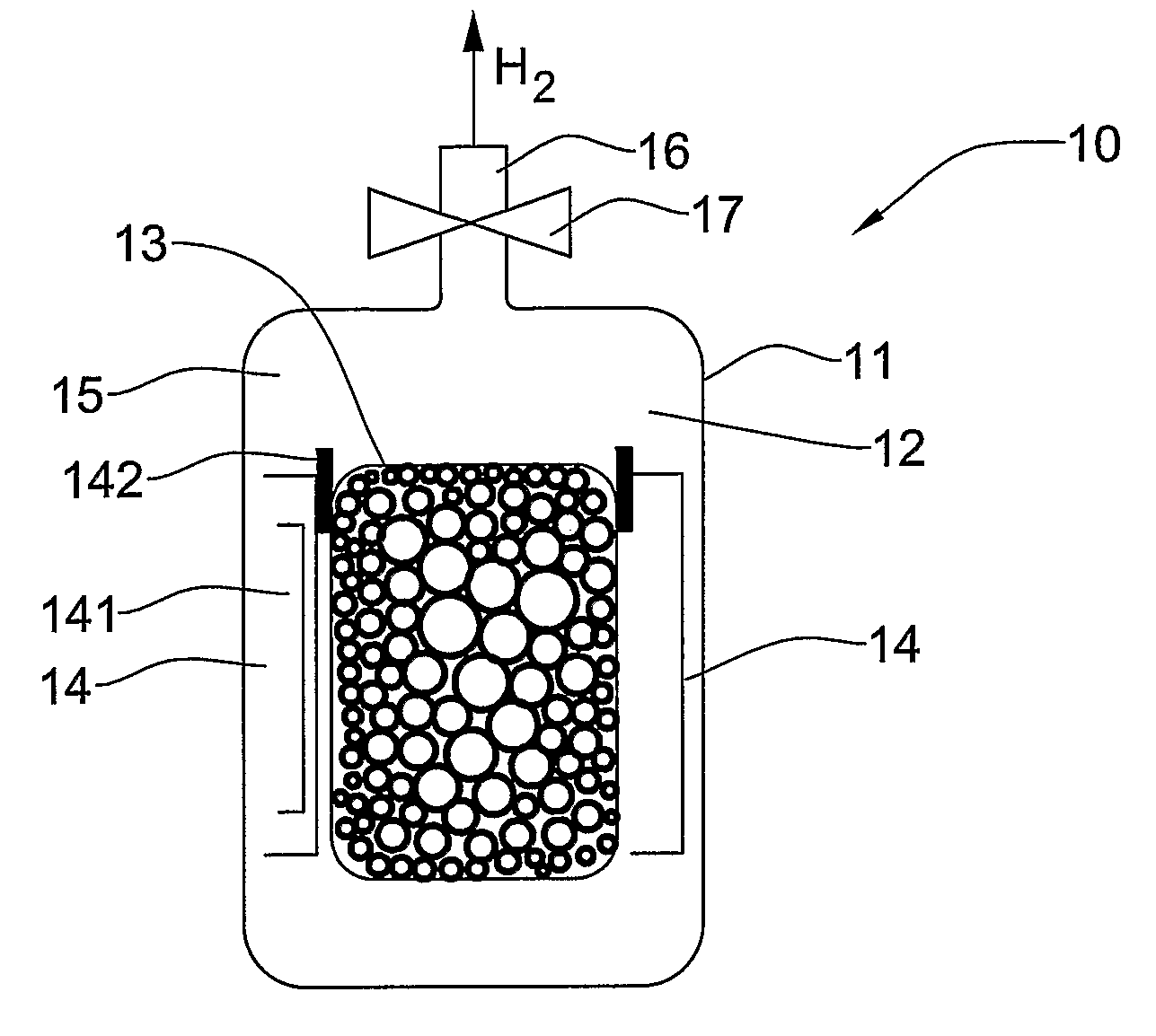
a hydrogen gas and tank technology, applied in the field of fuel storage, can solve the problems of high heat consumption, high loss of hydrogen evaporation, and time-consuming to start working, and achieve the effects of reducing hydrogen gas loss, increasing safety and cost-saving, and high hydrogen weight conten

Active Publication Date: 2010-01-19
CEN CO LTD +1
View PDF22 Cites 5 Cited by
  • Summary
  • Abstract
  • Description
  • Claims
  • Application Information

AI Technical Summary

Benefits of technology

The solution achieves higher hydrogen weight content, reduced storage pressure and temperature requirements, and lower hydrogen losses, enhancing safety and cost-effectiveness while maintaining strength properties.

Problems solved by technology

One of the problems of hydrogen energetics is safe storage and delivery of hydrogen fuel to a combustion -cell.
However, about one third of hydrogen energy (11 kW•hour / kg H2) is consumed to reach this temperature, while hydrogen evaporation losses can reach 3-5% daily.
However, these techniques are inertial, and it takes time for them to start working (several minutes).
Moreover, hydrogen absorption and release consume a lot of heat.
The main drawbacks of this tank are related to explosion hazards, relatively low hydrogen content per vessel volume unit, and gas losses due to-gas release from the tank.
The main drawback of this method is in the fact that the microspheric accumulator cannot be charged at very high hydrogen pressures and high temperatures, because it makes the process hazardous due to the low tensile strength of glass, which is within 20 kg / mm2.
This does not allow hydrogen weight content in the microspheres to be substantially higher than 6% (by weight).

Method used


Image

  • Tank and material for storage of hydrogen gas
  • Tank and material for storage of hydrogen gas
  • Tank and material for storage of hydrogen gas

Examples


example 1

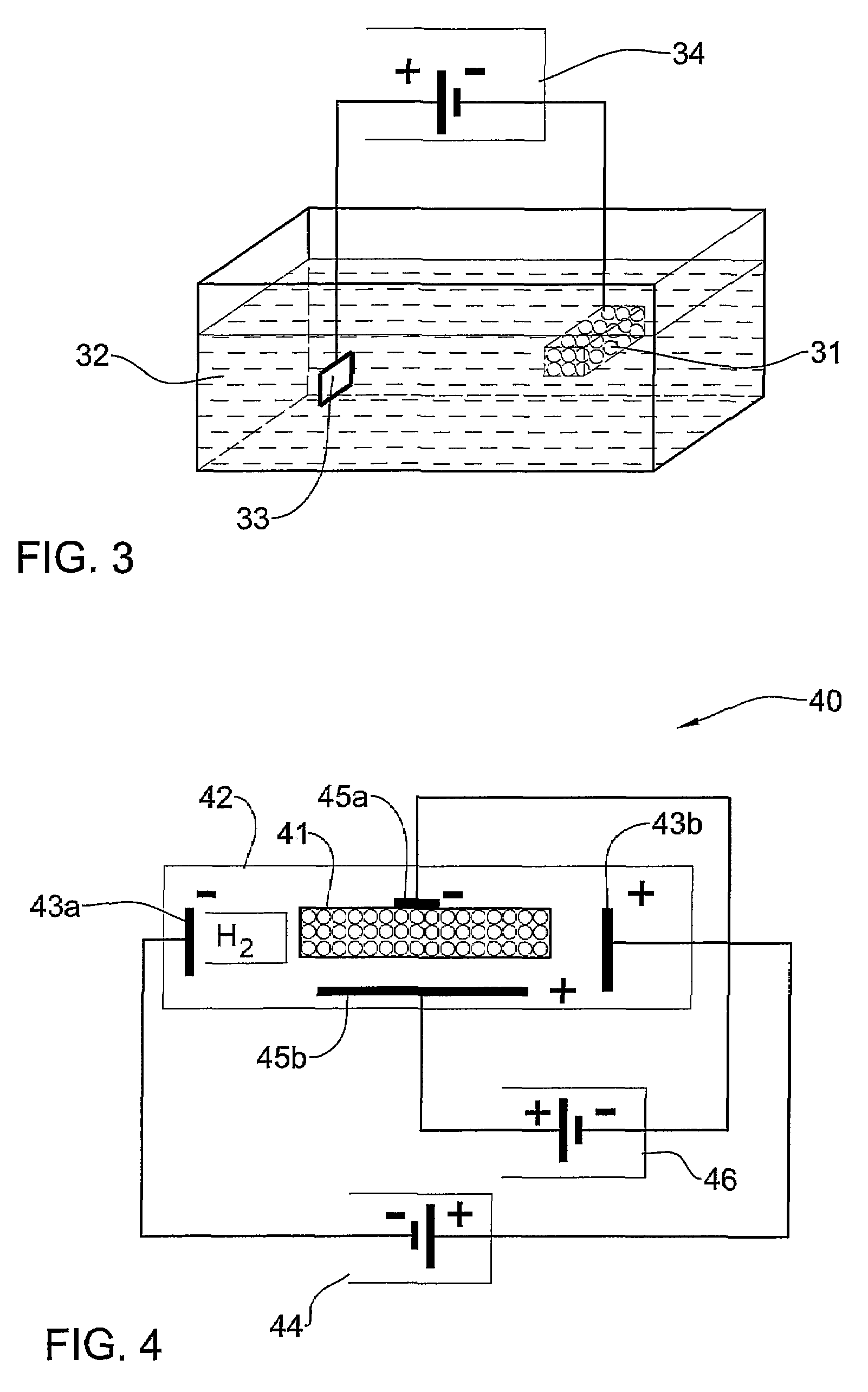
[0091]EI-647 steel 10 μm granules of microspheres in the volume of 2 ml were hydrogen-filled at room temperatures in 4% sulfuric acid water solution. Electrolysis proceeded for 1 hour with electrode potential 2V higher than water decomposition potential. Once the process was completed, granules were washed with desalted water and air-dried at room temperatures.

[0092]To calculate the hydrogen accumulated, granules were placed into a sealed pressure gauge-equipped vial. Granules were heated up to 300° C., following which they were cooled down to room temperatures, with hydrogen pressure measured in the vial. According to the measurements and calculations, 2400 ml hydrogen were released from 1 ml microspheres, which is close to nominal value and matches to 6000 atm hydrogen pressure in granules (see Table 5). This is equivalent to hydrogen weight content of 7.1%.

example 2

[0093]A similar test was conducted with 10 μm microspheres made of AT-3 titanium alloy. The hydrogen amount of 1200 ml was released from 1 ml microspheres, which is equivalent to hydrogen weight content of 6.3% w.

example 3

[0094]To facilitate hydrogen saturation of the microspheres, the latter were chemically coated with 0.1 μm layer of palladium. Hydrogen saturation was 3-4 times as intensive as in non-coated microspheres.

[0095]Referring to FIG. 4, a schematic illustration of a system for filling a microspheric material 41 with hydrogen by hydrogen ionization in electric discharge is illustrated. The microspheric material 41 is placed in a sealed vessel 42 made of electrically non-conductive material, such as glass, plastic, ceramic, etc. The vessel 42 is vacuumed, for example, by a vacuum booster pump to remove air, following which it is fed with hydrogen gas to an excess pressure of about 1-1000 atm. The system 40 includes a first pair of electrodes 43a and 43b arranged in the vessel 42 and coupled to a high voltage source (e.g., 10 kV-20 kV) 44. The electrodes 43a and 43b are configured for providing an electric discharge when the high voltage is applied thereto. The electric discharge will bring ...


PUM

PropertyMeasurementUnit
diameteraaaaaaaaaa
pressureaaaaaaaaaa
pressureaaaaaaaaaa

Abstract

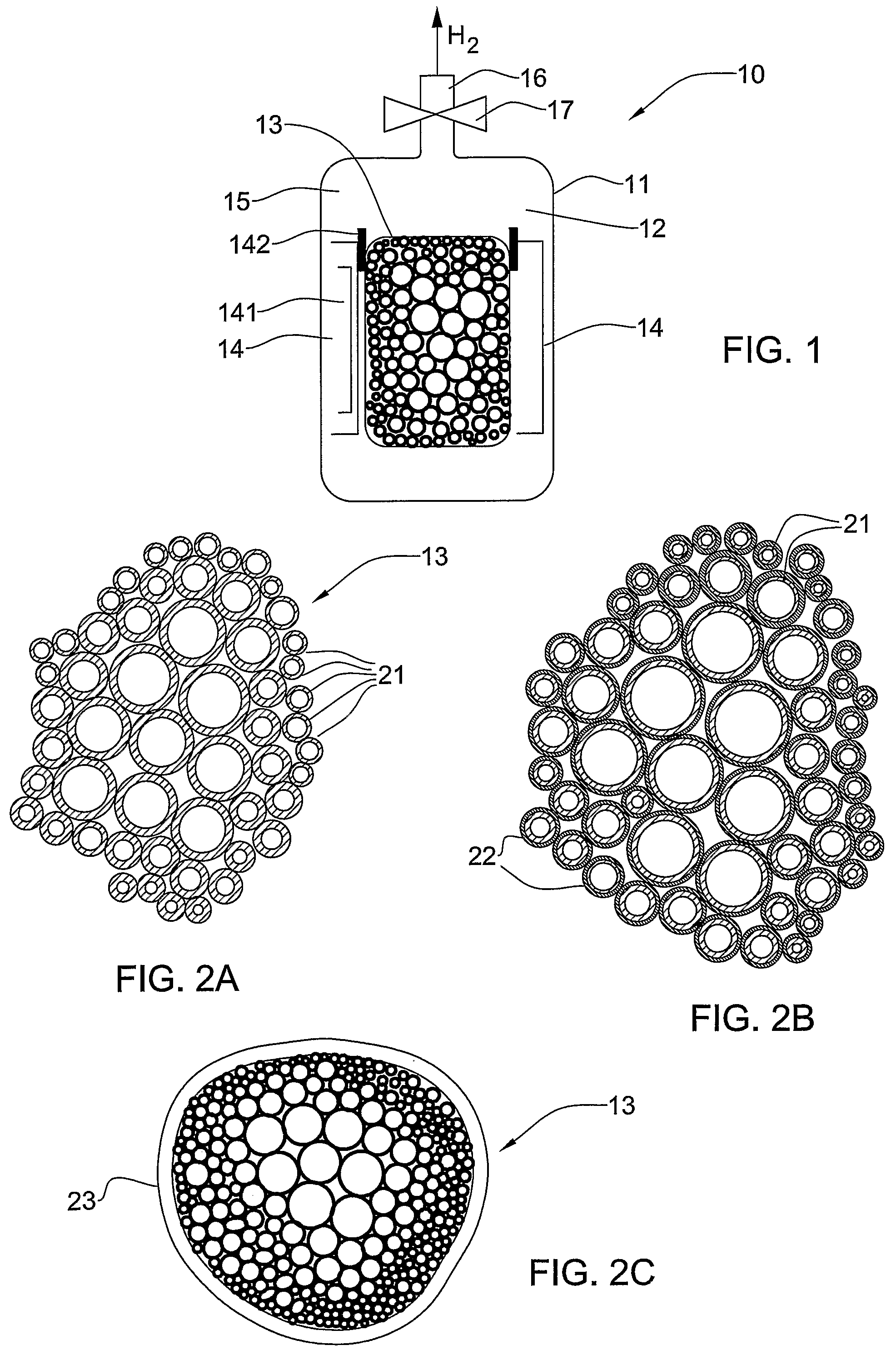
A hydrogen accumulation and storage material and a method of forming thereof are provided. The material comprises a plurality of various-sized and at least partially permeable to hydrogen microspheres bound together to form a rigid structure in which a diameter of the microspheres is reduced from a center of the structure towards edges of the structure. An outer surface of the rigid structure can be enveloped by a sealing layer, thereby closing interspherical spaces.

Description

FIELD OF THE INVENTION[0001]The present invention relates generally to fuel storage, and in particular, to accumulation and storage of hydrogen gas.BACKGROUND OF THE INVENTION[0002]It is well-known that hydrogen is a very efficient and clean-burning fuel. Hydrogen can be combined with oxygen through combustion, or through fuel cell mediated oxidation / reduction reactions, to, produce heat, or electrical power. The primary product of this reaction is water, which is non-polluting and can be recycled to regenerate hydrogen and oxygen.[0003]Currently, hydrogen energetics is the focus of interest in nuclear industry, motor transport, auto industry, chemical industry, aerospace industry, portable power sources industry (cellular phones, computers, home appliances), etc. In particular, the transport sector is a consumer of about half of the world's crude oil production. Therefore, this sector of the economy is intensively adopting the use of hydrogen fuel. This would solve environmental pr...

Claims


Application Information

Patent Timeline
Patent Type & Authority Patents(United States)
IPC IPC(8): B01D59/26
CPCC01B3/0005C01B3/001F17C11/005Y02E60/321Y10S502/526Y02E60/327Y10T428/268Y10S420/90Y02E60/325Y10T137/0318Y02E60/32C01B3/00F17C11/00F17C5/04
Inventor CHABAK, ALEXANDER
Owner CEN CO LTD
Learn More