Apparatus and cartridge for storage of compressed hydrogen gas

a hydrogen gas and compressed gas technology, applied in the field of fuel storage, can solve the problems of increasing increasing the cost of storage, so as to achieve the effect of reducing the loss of hydrogen gas on storage, and increasing the weight content of hydrogen

Active Publication Date: 2012-05-01
CEN CO LTD +1
View PDF18 Cites 0 Cited by
  • Summary
  • Abstract
  • Description
  • Claims
  • Application Information

AI Technical Summary

Benefits of technology

[0012]Despite known techniques in the area of accumulation and storage of hydrogen in micro-containers, there is still a need in the art for further improvement in order to provide a safe hydrogen storage at higher pressure, higher weight content of hydrogen, lower losses of hydrogen on storage as well as sufficient hydrogen load and release rates in operation, which will result in increased safety and cost-saving. Moreover, it would be advantageous to have a novel apparatus for storage of compressed hydrogen gas in which the rate of liberation of hydrogen gas can be controllably varied.

Problems solved by technology

One of the problems of hydrogen energetics is safe storage and delivery of hydrogen fuel to a combustion cell.
Nevertheless, most compressed gaseous storage tanks are relatively large and heavy.
Moreover, existing accumulation techniques with compressed gaseous hydrogen in tanks provide a relatively low hydrogen weight content (the ratio of the weight of hydrogen in accumulator to the weight of accumulator), i.e., less than 10 weight %, and there are certain restrictions for further growth of this parameter along with low explosion protection.
Disadvantages of metal hydride storage are that depending on the type of metal alloy, more or less elevated temperatures are needed to set hydrogen free again, and the low mass related storage density.
However, due to the weaker bonding of hydrogen in these solids the storage temperatures have to be lower than those for storage as metal hydrides.

Method used


Image

  • Apparatus and cartridge for storage of compressed hydrogen gas
  • Apparatus and cartridge for storage of compressed hydrogen gas
  • Apparatus and cartridge for storage of compressed hydrogen gas

Examples


Embodiment Construction

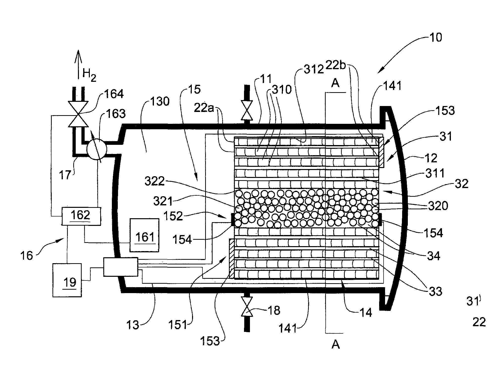
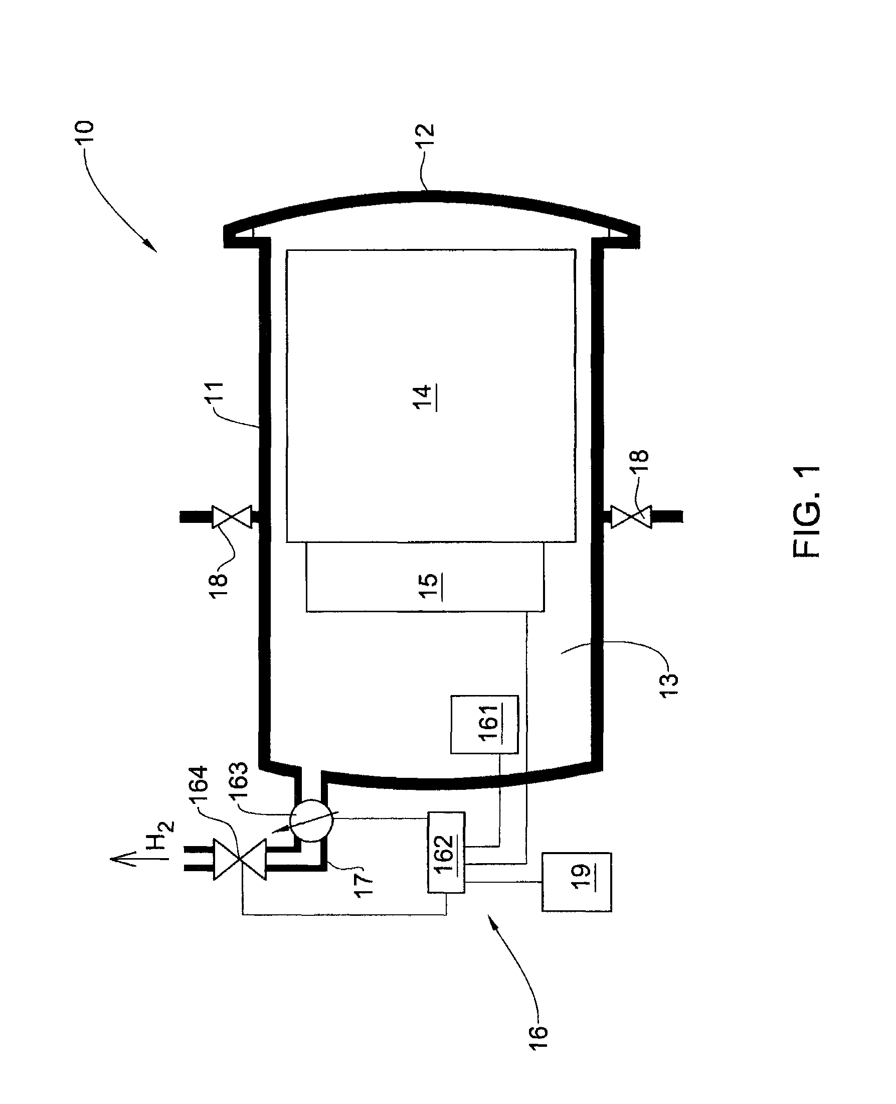
[0039]The principles and operation of an apparatus for storage hydrogen gas according to the present invention may be better understood with reference to the drawings and the accompanying description. It should be understood that these drawings are given for illustrative purposes only and are not meant to be limiting. It should be noted that the figures illustrating various examples of the apparatus of the present invention are not to scale, and are not in proportion, for purposes of clarity. It should be noted that the blocks as well other elements in these figures are intended as functional entities only, such that the functional relationships between the entities are shown, rather than any physical connections and / or physical relationships. The same reference numerals and alphabetic characters will be utilized for identifying those components which are common in the hydrogen storage apparatus and its components shown in the drawings throughout the present description of the inven...


PUM

PropertyMeasurementUnit
cryogenic temperaturesaaaaaaaaaa
temperatureaaaaaaaaaa

Abstract

An apparatus for storage of compressed hydrogen gas is provided. The apparatus includes a sealed housing having an outlet pipe coupled to the housing and equipped with a controllable discharge valve. The sealed housing defines a chamber that includes a cartridge comprising an assembly of at least two different types of micro-containers configured for accumulating and storing said compressed hydrogen gas. The apparatus also includes a hydrogen liberating tool configured for controllable liberating the hydrogen gas from the cartridge into a volume of the chamber that is not occupied by the cartridge. The apparatus is controlled by a control system operatively coupled to the controllable discharge valve and the hydrogen liberating tool, and configured for controlling operation thereof.

Description

FIELD OF THE INVENTION[0001]The present invention relates generally to fuel storage, and in particular, to accumulation and storage of hydrogen gas.BACKGROUND OF THE INVENTION[0002]It is well-known that hydrogen is a very high energy density element and clean-burning fuel. The energy density of hydrogen, which is around 120 MJ / kg, is more than double that of most conventional fuels, e.g., natural gas: 43 MJ / kg and gasoline 44.4 MJ / kg. Hydrogen can be combined with oxygen through combustion, or through fuel cell mediated oxidation / reduction reactions, to produce heat, or electrical power. The primary product of this reaction is water, which is non-polluting and can be recycled to regenerate hydrogen and oxygen.[0003]Currently, hydrogen energetics is the focus of interest in nuclear industry, motor transport, auto industry, chemical industry, aerospace industry, portable power sources industry (cellular phones, computers, home appliances), etc. In particular, the transport sector is a...

Claims


Application Information

Patent Timeline
Patent Type & Authority Patents(United States)
IPC IPC(8): F17C1/00
CPCC01B3/0005C01B3/001C01B3/0084F17C11/005Y02E60/321Y02E60/327Y02E60/32C01B3/00F17C11/00
Inventor CHABAK, ALEXANDER
Owner CEN CO LTD
Why Eureka
Try Eureka