
Composite data detector and a method for detecting data

a composite data and detector technology, applied in the field of data detectors, can solve the problems of large amount of power consumption, large amount of heat generation, and the chip package that contains the data detector is not designed to handle the excess heat, so as to improve the overall accuracy of the composite detector, reduce the period of time of the second detector, and improve the reliability of the new hard bit estimate

Inactive Publication Date: 2010-01-12
AVAGO TECH INT SALES PTE LTD
View PDF16 Cites 87 Cited by
  • Summary
  • Abstract
  • Description
  • Claims
  • Application Information

AI Technical Summary

Benefits of technology

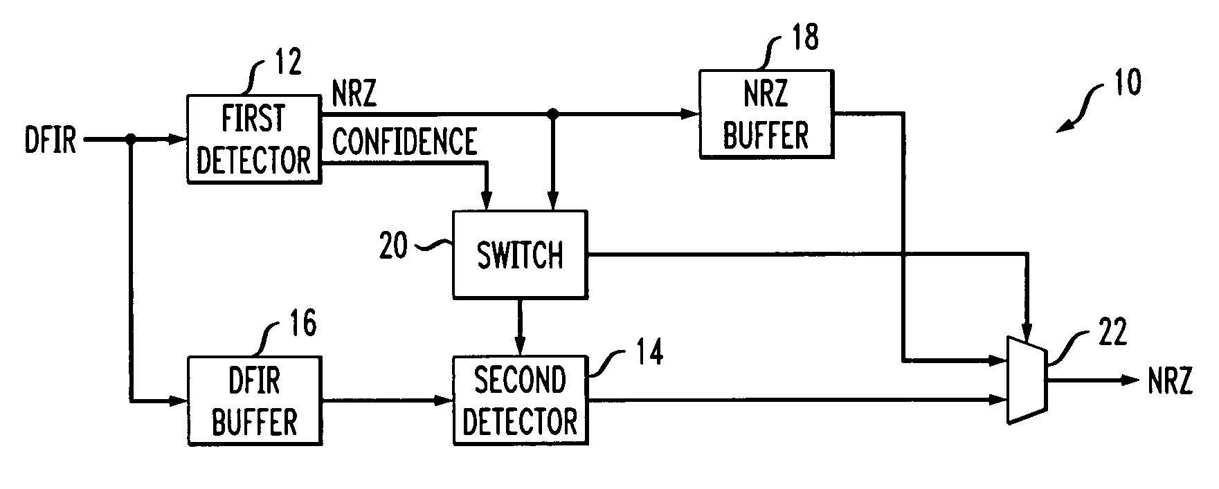
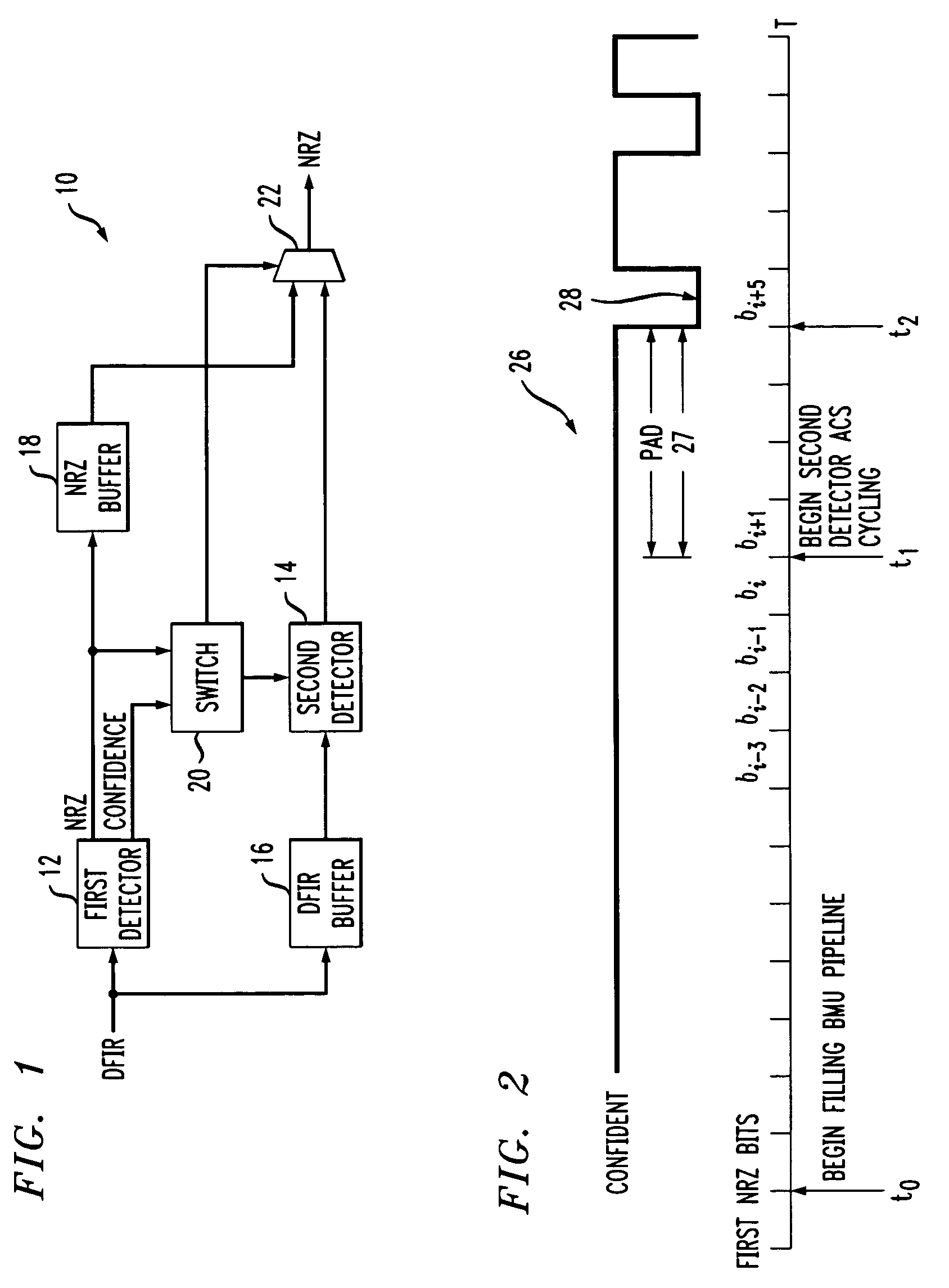
The present invention provides a composite data detector for detecting data and a method for detecting data. The composite data detector comprises two data detectors: a first data detector and a second data detector. The first data detector receives a sequence of bits and generates hard bit estimates and corresponding confidence factors indicating the reliability of each hard bit estimate. The second data detector receives the same sequence of bits a predetermined delay period after the first data detector. The second data detector processes the unreliable hard bit estimates based on a branch metrics processing algorithm to generate new, reliable hard bit estimates. The second data detector is initialized to a known state prior to processing the bit sequence to improve reliability and accuracy. The technical effects of the invention include improved accuracy and reliability of data detection and reduced processing time of the second data detector.

Problems solved by technology

A recurring problem with existing data detectors is that they generally consume a large amount of power to achieve adequate performance, which, in turn, generates a large amount of heat.
Typically, the chip package that contains the data detector is not designed to handle the excess heat caused by the large amount of power consumed.
Although standard data detectors that consume less power exist, they generally sacrifice performance in order to save power.
However, known composite detectors have several drawbacks, including poor efficiency.
The minimum runtime of the larger detector causes it to run more often than necessary, which wastes power.
Moreover, the larger detector is initiated based on path metric differences, which may not always be accurate.
In the case where the larger detector is a parity-doubled Viterbi detector, no provision is made to resynchronize the larger detector in the correct parity state, which results in errors.

Method used


Image

  • Composite data detector and a method for detecting data
  • Composite data detector and a method for detecting data
  • Composite data detector and a method for detecting data

Examples


Embodiment Construction

[0021]In accordance with the present invention, a composite data detector is provided that estimates bits with very high precision and which is very efficient in terms of power consumption. In contrast to the known composite data detector, which has a second detector that starts in an unknown state after being triggered by the smaller detector and has a fixed runtime of a minimum of 60 cycles, the second detector of the invention starts in a known state and only runs as long as is necessary before being switched off and handing control back over to the smaller detector. Therefore, the composite data detector of the invention consumes less power than the known composite data detector and estimates bits with higher accuracy. The composite data detector of the invention in accordance with exemplary embodiments will now be described with reference to FIGS. 1-10.

[0022]FIG. 1 illustrates a block diagram of an example of the composite data detector 10 of the present invention. The composit...


PUM


Abstract

A composite data detector having first and second data detectors. The second detector of the invention starts in a known state and only runs as long as is necessary before being switched off and handing control back over to the smaller detector. Therefore, the composite data detector of the invention consumes less power than the known composite data detector and estimates bits with higher accuracy.

Description

FIELD OF THE INVENTION[0001]The invention relates generally to the field of data detectors, and more particularly, to a composite data detector having a first data detector that runs continuously and a second detector that runs only when the confidence associated with an estimate made by the first detector is low. The composite data detector of the invention has relatively low power consumption and improved accuracy compared to existing composite data detectors.BACKGROUND OF THE INVENTION[0002]Digital communications systems and digital storage systems (e.g., hard disk drives) are similar from the perspective of extracting the original (transmitted or stored) bits from the received signal or from the readback signal. In the case of communication channels, the digital information is transferred from one location to another location, but at the same time (perhaps with a small transmission delay), whereas in storage channels, the information is transferred from one time to a later time,...

Claims


Application Information

Patent Timeline
Patent Type & Authority Patents(United States)
IPC IPC(8): H04L27/06
CPCG11B20/10009H04L25/03318H04L25/067
Inventor ASHLEY, JONATHAN JAMESBURGER, JR., HARLEY F.
Owner AVAGO TECH INT SALES PTE LTD
Learn More