
Low frequency electro-mechanical impedance tuner

a low-frequency electromechanical and impedance tuner technology, applied in the direction of impedence networks, instruments, measurement devices, etc., can solve the problems of prohibitive sizes, impossible to manufacture in one piece, and even unhandling of tuners, and achieve compact size and convenient manufacture.

Inactive Publication Date: 2010-01-12
TSIRONIS CHRISTOS
View PDF5 Cites 37 Cited by
  • Summary
  • Abstract
  • Description
  • Claims
  • Application Information

AI Technical Summary

Benefits of technology

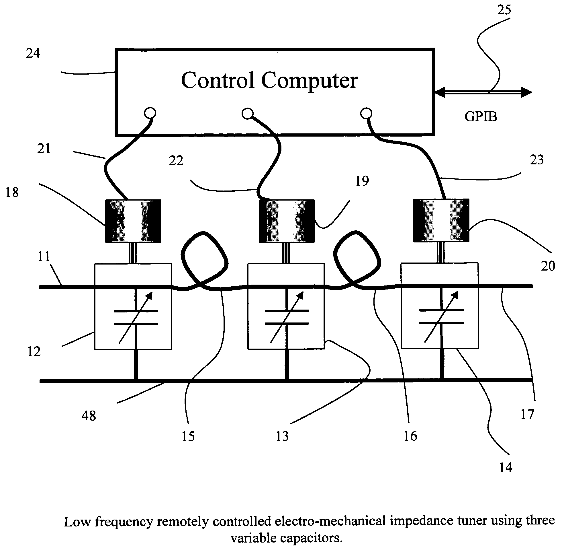
[0021]This invention describes a radio frequency, computer controlled electro-mechanical impedance tuner apparatus, which is compact in size, easily manufacturable, can be calibrated using standard measurement techniques and allows synthesizing impedances at various frequencies in the range of 10 to 200 MHz.

Problems solved by technology

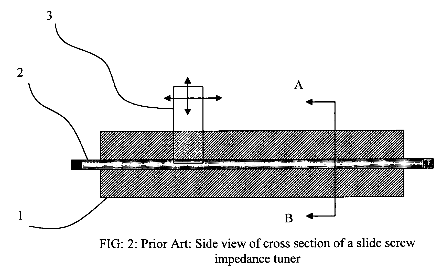
For lower frequencies the required length and thus the size of the tuner becomes even un-handier (3 meters for 50 MHz, 4.5 meters for 33 MHz and so on.) and practically impossible to manufacture in one piece.
In view of the required precision of such a tuner these sizes are prohibitive.
Typical transistors having higher gain at low frequencies have the tendency to generate spurious oscillations when presented with high reflection factors at these frequencies.
At low frequencies the unit becomes big, un-handy and difficult to manufacture; in addition to the fact, that its frequency coverage remains limited and non-adjustable.
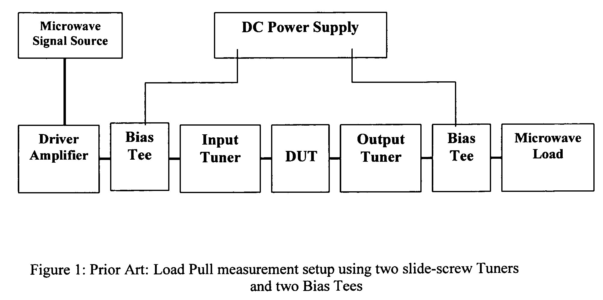
A further disadvantage of the multi-stub tuners is the fact that the variable shorts (5,6,7) do not allow DC bias to flow through the tuner in order to bias the DUT; this creates additional DC supply requirements for the test fixture, in which the DUT is embedded (FIG. 1).
In addition, a multi-stub tuner requires to insert the bias tees (FIG. 1) between the DUT and tuner, which, in turn, reduces the tuning range, because the bias tees introduce additional insertion loss between the tuner and the DUT.
Further-on the shorted parallel stubs in such tuners do not have the benign “low-pass” behavior of the slide screw tuners, since they represent a high reflection (a “short circuit”) at high as well at low frequencies, causing many test devices to oscillate or even fail, in which case the testing becomes impossible.

Method used


Image

  • Low frequency electro-mechanical impedance tuner
  • Low frequency electro-mechanical impedance tuner
  • Low frequency electro-mechanical impedance tuner

Examples


Embodiment Construction

[0043]This invention describes an electro-mechanical impedance tuner that can operate successfully at frequencies as low as 10 MHz and as high as 200 MHz. The reason for the low frequency limit lies in the fact that the required capacitance values are of the order of 2000 pF, a value which is not easily obtainable using mechanically adjustable capacitors with air as a dielectric. If higher value capacitors are available the concept is extendable to lower frequencies as well. Using dielectrically loaded capacitors (for instance with high dielectric oil or dielectric foil between the conductive plates) represents a valuable alternative for very low frequencies; the mechanics of such capacitors may though be prone to intense maintenance and demand expensive manufacturing.

[0044]The high frequency limit for this apparatus lies in the fact that the RF cables required to interconnect the capacitance blocks and the interconnections themselves will introduce insertion losses, which will degr...


PUM


Abstract

A segmented, electro-mechanical, remotely controlled programmable impedance tuner for the frequency range between 10 and 200 MHz uses a cascade of three continuously variable mechanical capacitors interconnected by a set of two low loss flexible or semi-rigid cables; the electrical length of the interconnecting cables between the capacitors determines the frequency at which tuning coverage of the entire area of the Smith chart is optimum; for maximum impedance coverage the length is to be chosen such as to generate a transmission phase shift of 60 degrees at the center frequency between each capacitor stage. Remote tuning is possible by changing the value of the capacitors using electrical stepper motors. The tuner is calibrated using a vector network analyzer and the data are saved in the memory of the control computer, which then allows tuning to any user defined impedance within the tuning range. Reflection factor values between 0 and higher than 0.9 can be obtained using this tuner.

Description

PRIORITY CLAIM[0001]Not ApplicableCROSS-REFERENCE TO RELATED ARTICLES[0002][1] ADS, Advanced Design System, Agilent Technologies; http: / / eesof.tm.agilent.com[0003][2] Microwave Office Microwave Office 2004 Design Suite; http: / / www.mwoffice.com[0004][3]“High Resolution Tuners eliminate load pull performance errors”, Application Note 15, Focus Microwaves, January 1995[0005][4]“Computer aided design of microwave circuits”, K. C. Gupta et al. Artech ISBN: 0-89006-105-X, Chapter 2.STATEMENT REGARDING FEDERALLY SPONSORED RESEARCH OR DEVELOPMENT[0006]Not ApplicableREFERENCE TO SEQUENCE LISTING, A TABLE, OR A COMPUTER PROGRAM LISTING COMPACT DISC APPENDIX[0007]Not ApplicableBACKGROUND OF THE INVENTION[0008]This invention relates to RF load and source pull testing of medium and high power RF transistors and amplifiers using remotely controlled electro-mechanical impedance tuners.[0009]Modern design of high power microwave amplifiers and mixers, used in various communication systems, requires...

Claims


Application Information

Patent Timeline
IPC IPC(8): H03H7/38G01R27/00
CPCG01R27/32H01P5/04H03H7/38
Inventor TSIRONIS, CHRISTOS
Owner TSIRONIS CHRISTOS
Learn More