Digital loop circuit for programmable logic device

a programmable logic device and loop circuit technology, applied in the direction of electrical apparatus, push automatic control, etc., can solve the problems of wasting loop circuitry, large area added to the pld, and large size of the loop circuit, so as to reduce the size and complexity

Inactive Publication Date: 2009-12-15
ALTERA CORP
View PDF21 Cites 45 Cited by
  • Summary
  • Abstract
  • Description
  • Claims
  • Application Information

AI Technical Summary

Benefits of technology

[0008]The present invention provides loop circuitry on a programmable logic device that is of reduced size and complexity by providing an all-digital loop circuit. Thus, an all-digital PLL in accordance with the invention includes a digital phase detector or phase-frequency detector, a digital loop filter and a digitally-controlled oscillator (DCO). The digital phase detector or phase-frequency detector and digital loop filter also can be used in an all-digital DLL.
[0009]The digital loop filter preferably directly uses the phase detector or phase-frequency detector output signals and preferably provides a digital output that serves as the integral path, and as the input to a separate proportional path. The digital phase detector or phase-frequency detector preferably provides an extended error range by providing different digital output signals for different ranges of phase and / or frequency error.

Problems solved by technology

Loop circuits are thus relatively large and complex circuits, and providing loop circuits on PLDs therefore either adds significant area to the PLD, or takes away area that could be used for programmable logic circuitry in a PLD of a given size.
This is of further concern because the loop circuits that are provided may not be used in a particular user design, so that, as far as that user is concerned, the loop circuitry is simply wasted.

Method used


Image

  • Digital loop circuit for programmable logic device
  • Digital loop circuit for programmable logic device
  • Digital loop circuit for programmable logic device

Examples


Embodiment Construction

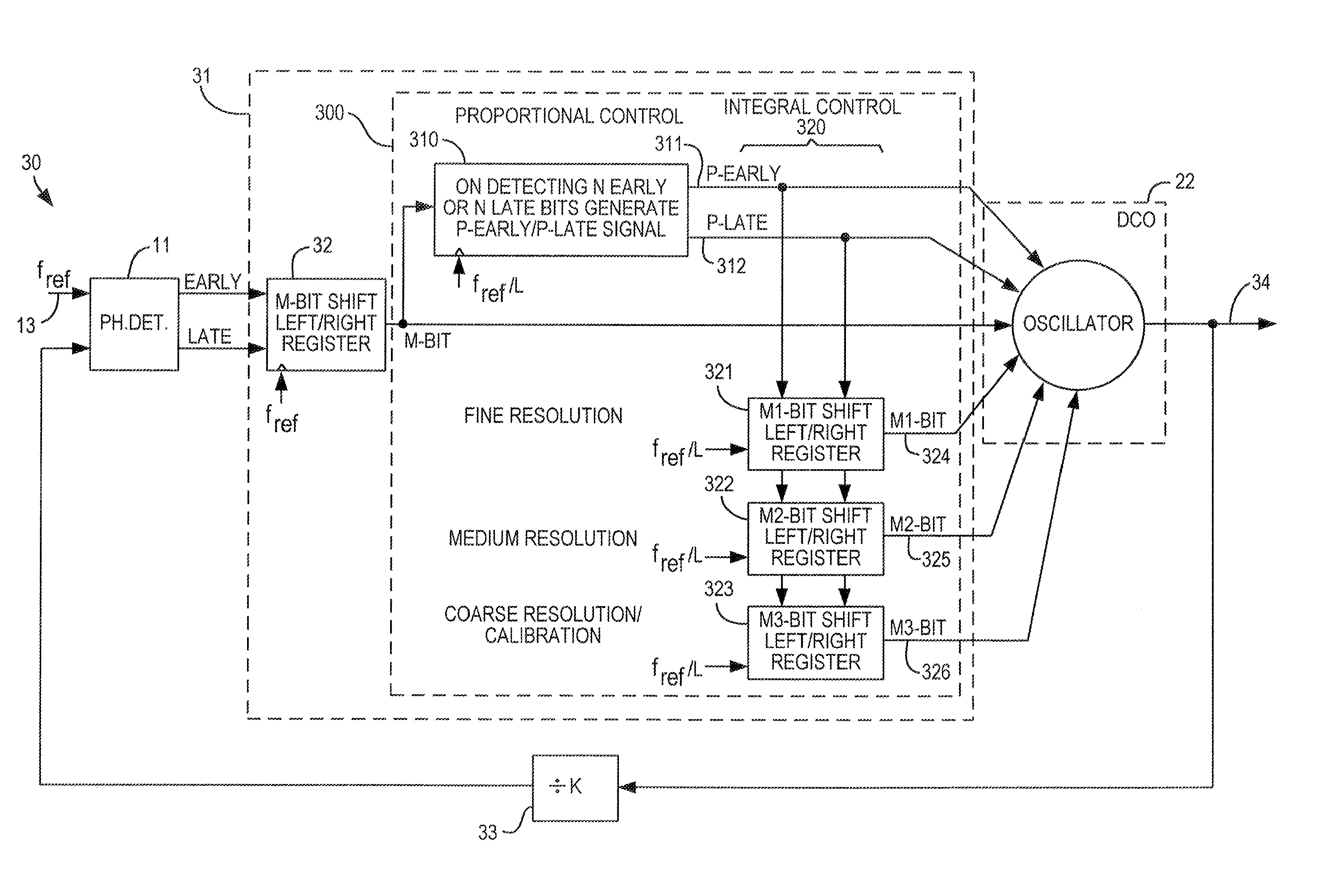
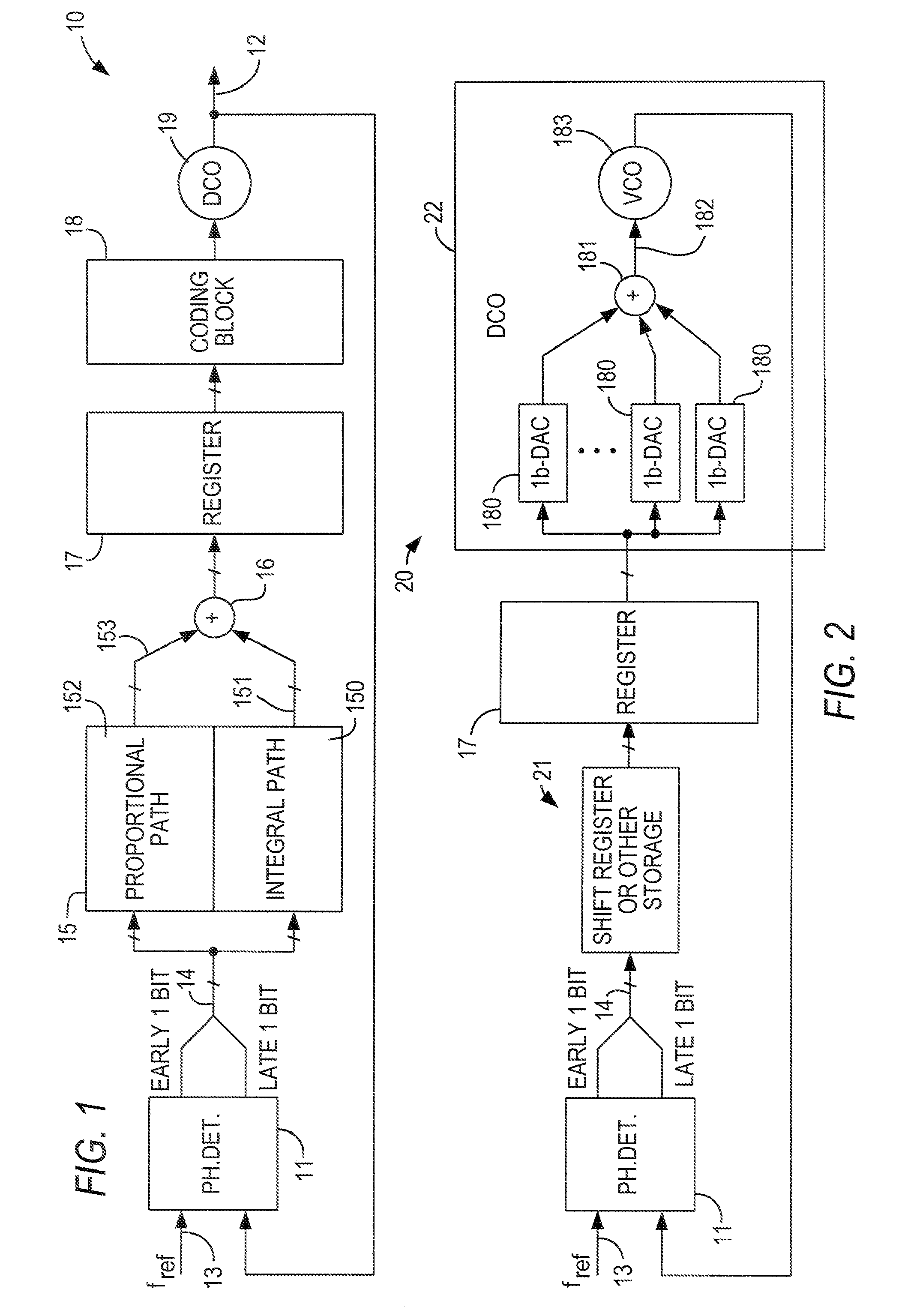
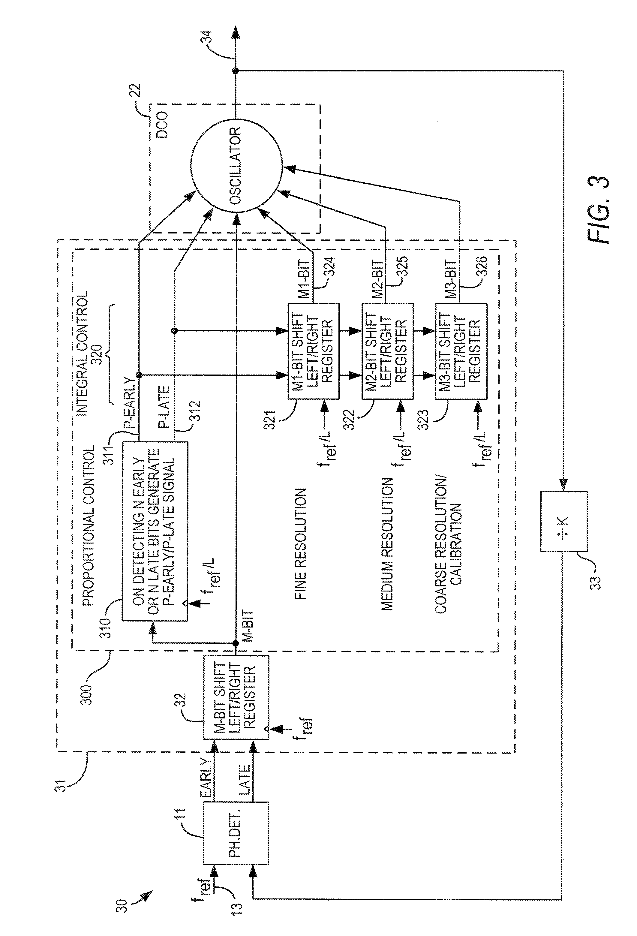
[0020]As described above, loop circuits such as PLLs are relatively large and complex. A traditional analog PLL includes a phase-frequency detector, a charge pump, a loop filter, and a voltage-controlled oscillator. Digital PLLs (DPPLs) are known, but known DPLLs remain large and complex, in part because they retain the various blocks of an analog PLL, but convert them, to varying degrees, to digital form. Thus, for example, a known digital loop filter may retain separate integral and proportional paths, necessitating a multi-bit adder to combine those paths into a single loop filter output.

[0021]In accordance with the present invention, a preferred embodiment of a substantially purely digital loop filter merely counts the early / late (i.e., retard / advance) signals from a digital phase detector, and outputs a signal to a digitally-controlled oscillator (DCO) only when the number of counts exceeds some threshold in one direction or the other. Known techniques could be applied to augme...


PUM


Abstract

A digital loop circuit—i.e., a phase-locked loop (“PLL”) or delay-locked loop (“DLL”)—having a simplified digital loop filter, is particularly well-suited for a programmable logic device (“PLD”). The loop filter may be a memory (e.g., a shift register) which counts the early / late or up / down signals from a phase detector or phase-frequency detector (“error detector”) and outputs a signal when the count exceeds a threshold. Separate integral and proportional paths of the loop may include chained shift registers, with each outputting a signal only when the previous shift register overflows into it. A digital error detector may respond nonlinearly, with outputs of different bit widths, to different amounts of phase or frequency error.

Description

CROSS REFERENCE TO RELATED APPLICATION[0001]This claims the benefit of commonly-assigned U.S. Provisional Patent Application No. 60 / 922,135, filed Apr. 6, 2007, which is hereby incorporated by reference herein in its entirety.BACKGROUND OF THE INVENTION[0002]This invention relates to digital loop circuits (i.e., phase-locked loops or delay-locked loops) having reduced complexity, and particularly to such loop circuits for use in a programmable logic device.[0003]It is known to incorporate phase-locked loop (“PLL”) and delay-locked loop (“DLL”) circuitry on programmable logic devices (“PLDs”). For example, it has become common for PLDs to accommodate various input / output standards, some of which require very accurate high-speed clocks. One way of providing such clocks is to provide loop circuitry on the PLD. Although the discussion that follows may concentrate primarily on PLLs, the present invention is applicable equally to DLLs.[0004]A basic PLL includes a phase-frequency detector ...

Claims


Application Information

Patent Timeline
Patent Type & Authority Patents(United States)
IPC IPC(8): H03L7/06
CPCH03L7/091H03L7/099H03L7/107H03L7/18H03L7/093H03L7/0812H03L7/0814H03L2207/06H03L7/0818
Inventor ZHUANG, JINGCHENGDU, QINGJINKWASNIEWSKI, TAD
Owner ALTERA CORP
Why Eureka
Try Eureka