Power take-off unit

a power take-off unit and power technology, applied in the direction of jet propulsion mounting, transportation and packaging, gearing, etc., can solve the problems of four-wheel drive power take-off units, bulky and complex power take-off units of this type, and difficulty in satisfying the demand, so as to reduce the number of parts, overall size and cost, and avoid the increase in complexity and bulk of the transmission or transaxle.

Active Publication Date: 2008-05-13
DYMOS
View PDF12 Cites 0 Cited by
  • Summary
  • Abstract
  • Description
  • Claims
  • Application Information

AI Technical Summary

Benefits of technology

[0015]One advantage of the present invention is that a power take-off unit is provided that has four-wheel drive capability and is employed with a transverse transmission or transaxle of a motor vehicle having reduced size and complexity compared to conventional units. Another advantage of the present invention is that the power take-off unit has a reduced number of parts, overall size, and cost. Yet another advantage of the present invention is that the power take-off unit provides a direct drive to one set of drive wheels without clutching mechanisms or planetary gear assemblies. A further advantage of the present invention is that the power take-off unit provides torque to four wheels as a separate unit, avoiding an increase to the complexity and bulk of the transmission or transaxle. Yet a further advantage of the present invention is that the power take-off unit has an overall reduction in the number of components, size, and weight, making the power take-off unit cost efficient.
[0016]Other features and advantages of the present invention will be readily appreciated, as the same becomes better understood, after reading the subsequent description taken in conjunction with the accompanying drawings.

Problems solved by technology

Satisfying this demand has been problematic in some types of vehicles, especially those with transverse mounted engines or transaxle type transmissions that drive the front wheels.
Known power take-off units of this type have the disadvantage of being bulky and complex.
This disadvantage of conventional four-wheel drive power take-off units arises from the inclusion of one or more clutch mechanisms and planetary gear assemblies that are employed to transfer torque to the drive assemblies that drive the front and rear wheels.
Additionally, providing the operative torque through one or more power take-off clutch devices and / or planetary gear assemblies increases the likelihood of mechanical failures.
In these examples, shifting the complexity and bulk of the power take-off unit into the transmission or transaxle or merely integrating the power take-off unit into the transmission or transaxle itself only further enlarges the size of the transmission and increases its complexity.
The underlying disadvantages still remain in the vehicle's drive train.
In any case, the size and complexity of the conventional four-wheel drive power take-off units makes it quite difficult to mount these devices in smaller more compact vehicles where physical space and ground clearance is already at a premium.
In this manner, attempting to simply reduce the size of the conventional power take-off units to allow them to fit within the physical restraints of a smaller motor vehicle is unacceptable as their load carrying capability is similarly reduced.

Method used


Image

  • Power take-off unit
  • Power take-off unit
  • Power take-off unit

Examples


Embodiment Construction

)

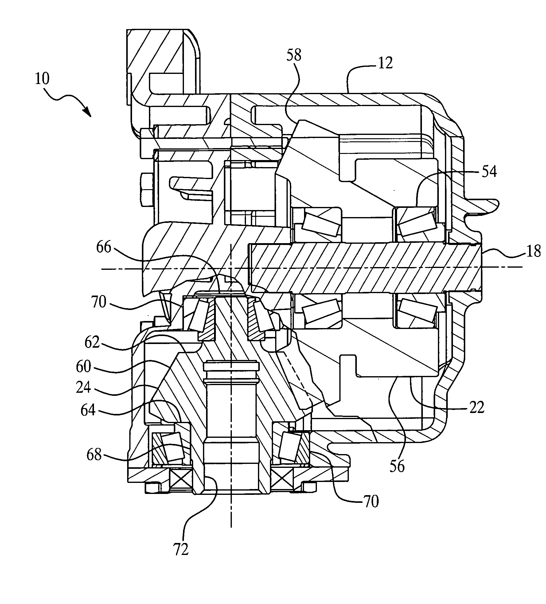
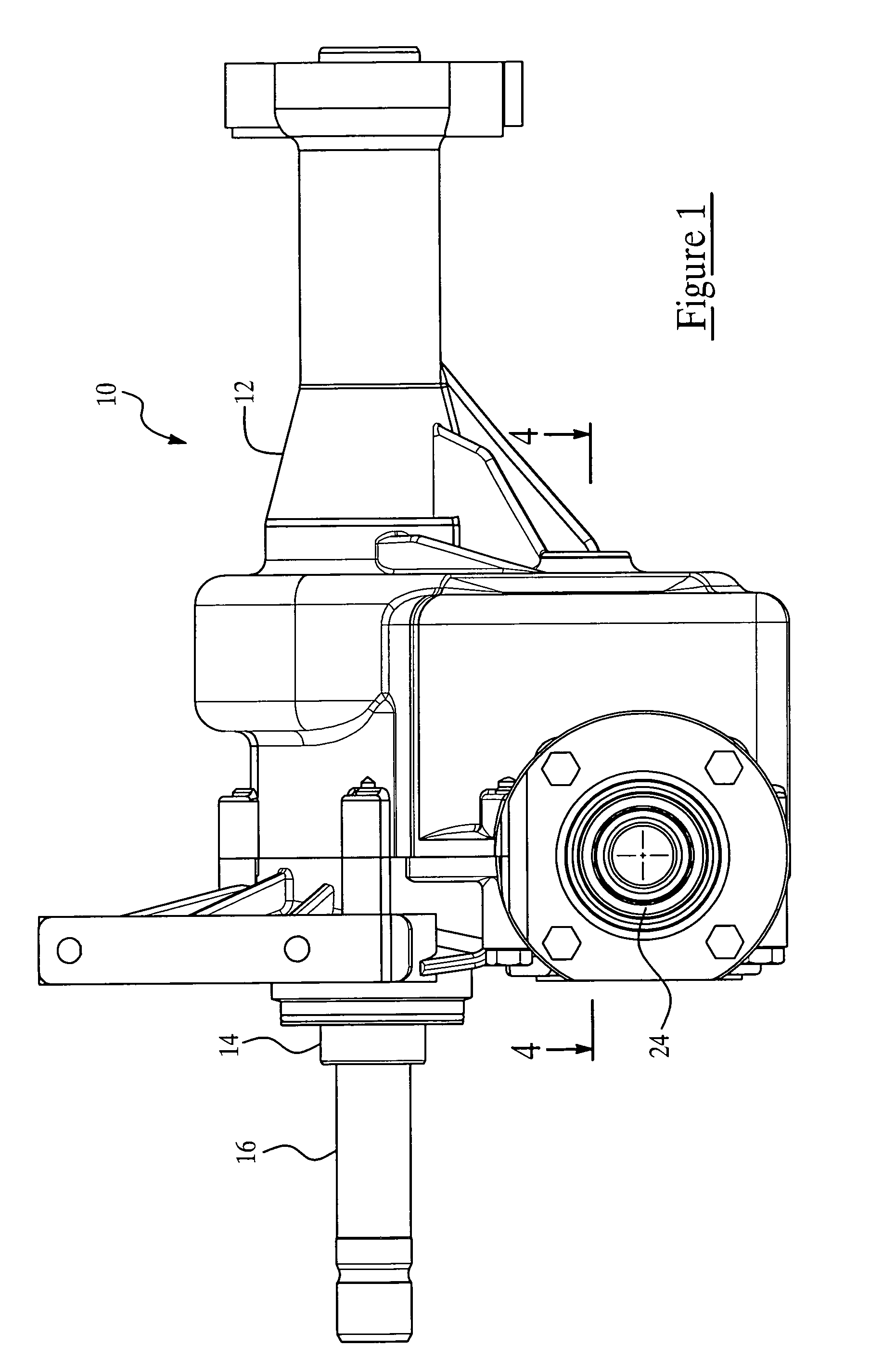
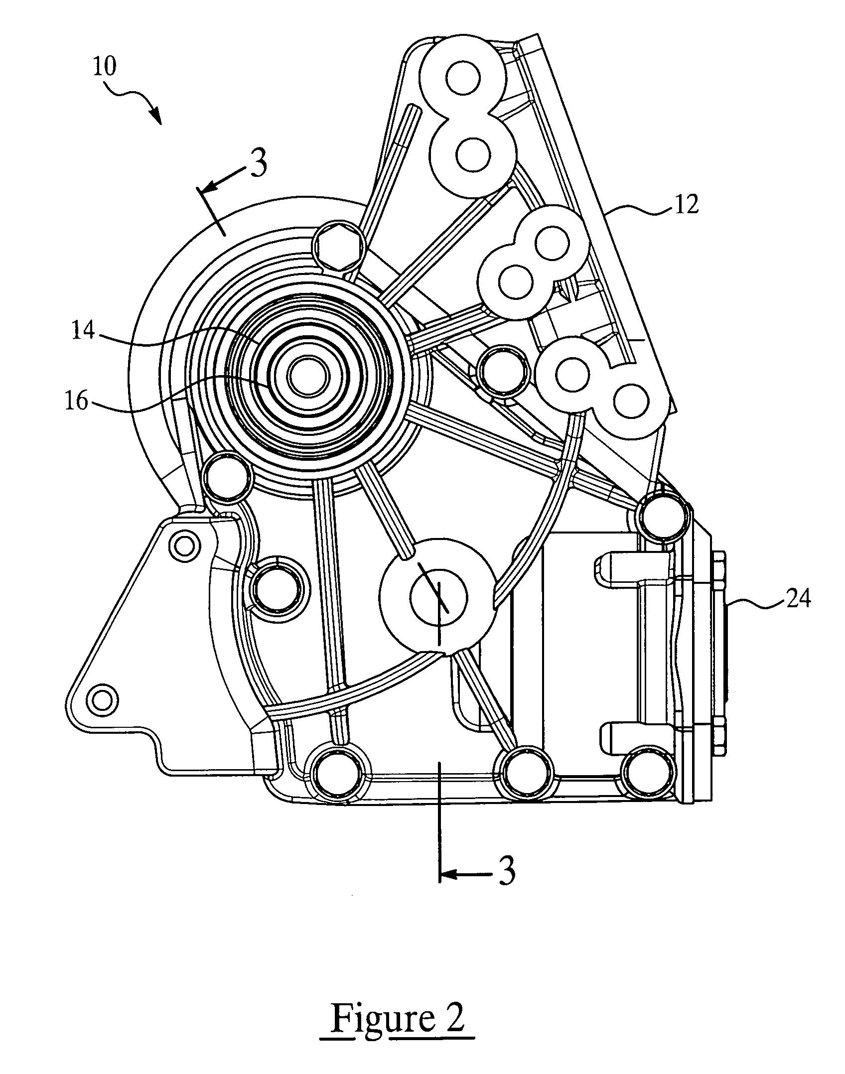
[0021]Referring to the Figures and in particular FIGS. 1 and 2, one embodiment of a power take-off unit 10, according to the present invention, is shown for a transmission (not shown) of a vehicle (not shown) such as a motor vehicle. The power take-off unit 10 includes a housing or case 12 for enclosing components of the unit 10. Specifically, the power take-off unit 10 includes an input shaft 14, a through shaft 16, a secondary shaft 18, a first drive gear 20, a second drive gear 22, and an output gear 24.

[0022]The power take-off unit 10 forms a portion of a vehicle powertrain and is responsible for taking the torque generated by a prime mover, such as an internal combustion engine, as delivered through a transmission and distribute it to drive all the wheels of the vehicle. As illustrated in FIG. 3, the input shaft 14 has an input end 30 and an output end 32. In one embodiment, the input shaft 14 also includes a longitudinal through-bore 38 that is adapted to slidingly receive an...


PUM


Abstract

A power take-off unit includes an input shaft for operative connection to a source of motive power and a first drive gear operatively mounted to the input shaft and having a first set of drive teeth. The power take-off unit also includes a second drive gear having a second set of drive teeth and a first set of bevel teeth, the second set of drive teeth being meshingly engaged to the first drive teeth. The power take-off unit further includes an output gear mounted transversely to the second drive gear and having a second set of bevel teeth meshingly engaged to the first set of bevel teeth to transfer torque transversely from the input shaft to drive a set of wheels of a vehicle.

Description

BACKGROUND OF THE INVENTION[0001]1. Field of the Invention[0002]The present invention relates generally to power take-off units and, more particularly, to a power take-off unit employed with a transmission of a vehicle to provide four-wheel drive capability.[0003]2. Description of the Related Art[0004]Generally speaking, land vehicles require three basic components. These components comprise a power plant (such as an internal combustion engine), a power train, and wheels. The internal combustion engine produces force by the conversion of chemical energy in a liquid fuel into the mechanical energy of motion (kinetic energy). The function of the power train is to transmit this resultant force to the wheels to provide movement of the vehicle.[0005]The power train's main component is typically referred to as the “transmission”. Engine torque and speed are converted in the transmission in accordance with the tractive-power demand of the vehicle. The vehicle's transmission is also capable...

Claims


Application Information

Patent Timeline
Patent Type & Authority Patents(United States)
IPC IPC(8): F16H37/06B60K17/344
CPCB60K17/344B60K5/04Y10T74/19665Y10T74/19098Y10T74/19074
Inventor BOWEN, THOMAS C.WRIGHT, NEDSTEFAN, DANENACHE, MARIUS
Owner DYMOS
Why Eureka
Try Eureka