Liquid crystal display panel with a continuous weir and a discontinuous weir covered by a sealing material
a technology of liquid crystal display panel and sealing material, which is applied in the direction of non-linear optics, instruments, optics, etc., can solve the problem of liquid crystal intruding into the sealing material through such a portion, and achieve the effect of preventing sealing failure and high reliability
- Summary
- Abstract
- Description
- Claims
- Application Information
AI Technical Summary
Benefits of technology
Problems solved by technology
Method used
Image
Examples
embodiment 1
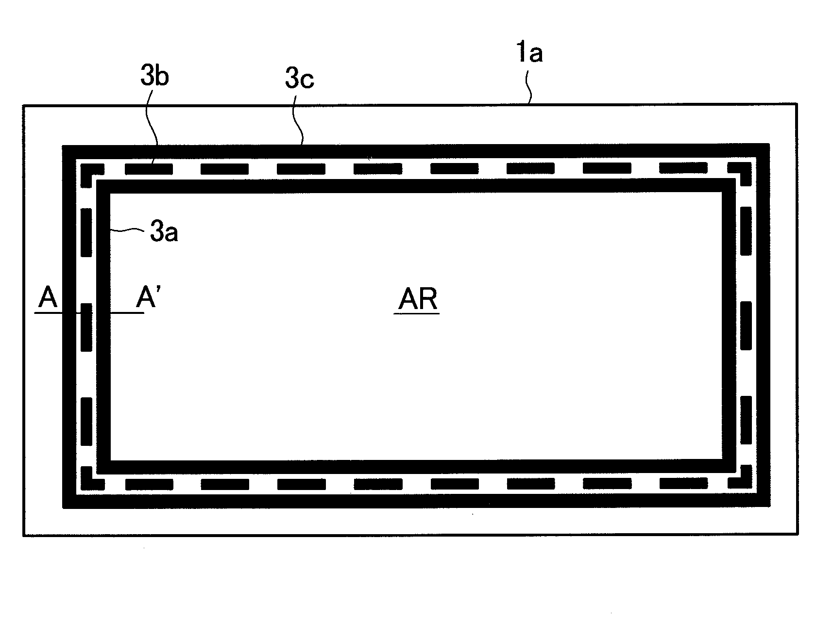
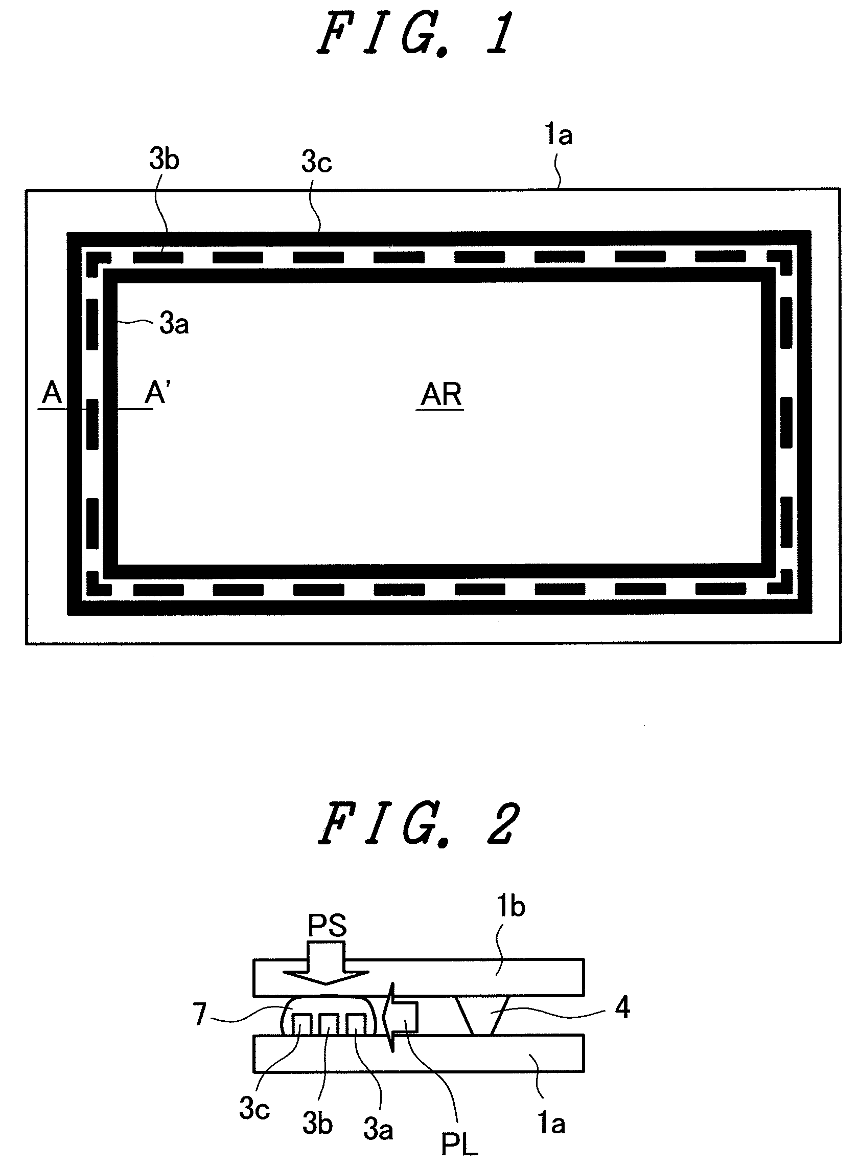
[0044]FIG. 1 is a plan view of one substrate for explaining a liquid crystal display panel of an embodiment 1 according to the present invention. Here, first, second and third weirs 3a, 3b and 3c are formed on an outer periphery of a display region AR of one substrate 1a which constitutes a TFT substrate.
[0045]Out of these weirs 3a, 3b and 3c, the innermost peripheral weir 3a and the outermost peripheral weir 3c are continuously formed over the entire circumference in a closed bank shape. Further, the weir 3b arranged between the innermost peripheral weir 3a and the outermost peripheral weir 3c is formed in a discontinuous shape including a plurality of gaps which traverse the surrounding direction of the weirs 3a, 3c.
[0046]FIG. 2 is a cross-sectional view taken along a line A-A′ in FIG. 1. As shown in FIG. 2, this embodiment is characterized in that the sealing material 7 is arranged in a state that the sealing material 7 covers the weirs 3a, 3b and 3c which are arranged on the TF...
embodiment 2
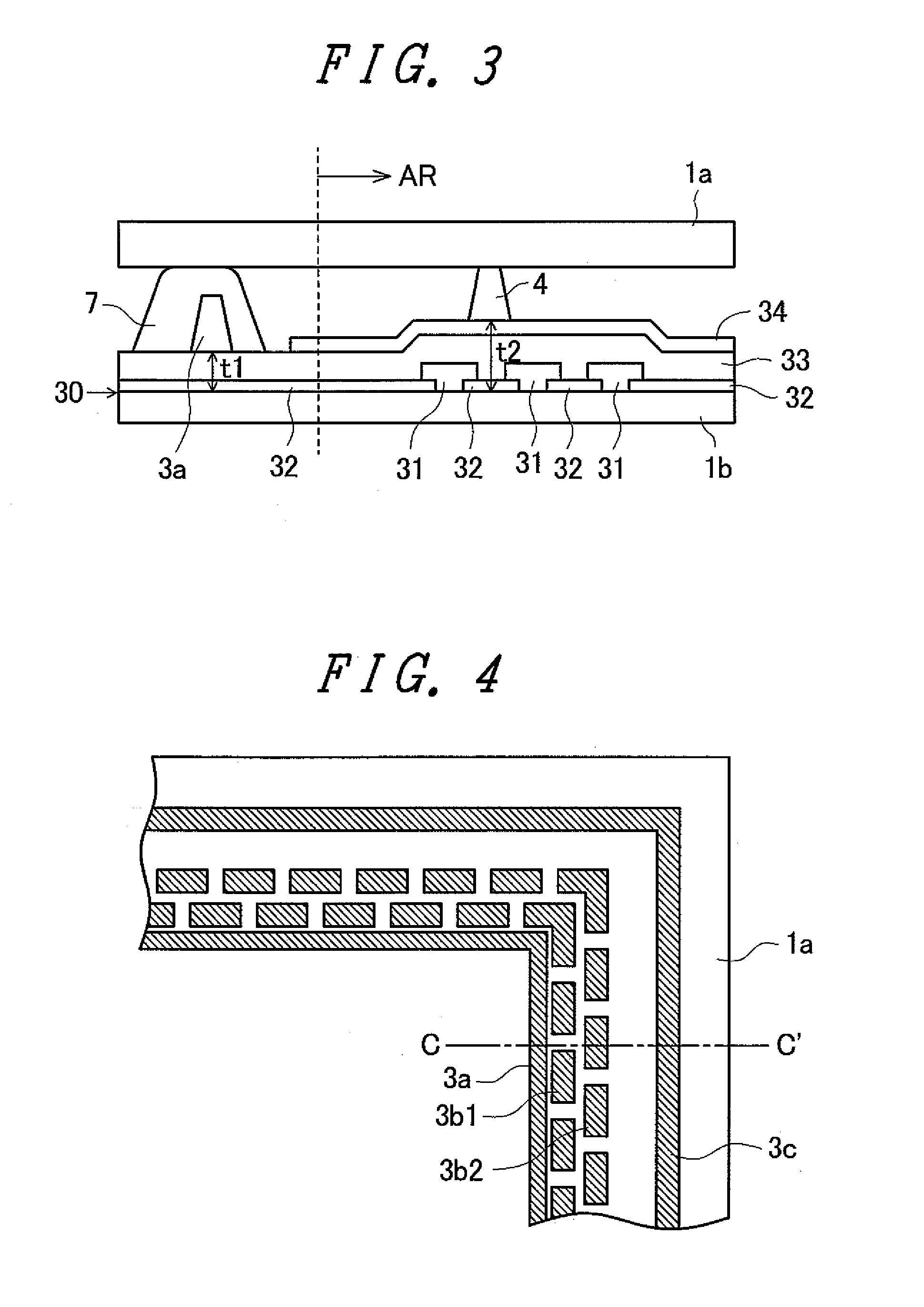
[0061]FIG. 4 is a view showing another embodiment of the present invention. FIG. 4 shows the constitution in which two intermediate weirs 3b1, 3b2 are arranged. FIG. 5 is a cross-sectional view taken along a line C-C′ in FIG. 4 showing one substrate together with another substrate. As shown in FIG. 4 and FIG. 5, an inner most peripheral weir 3a and an outermost peripheral weir 3c are made of a closed weir. That is, the innermost peripheral weir 3a and the outermost peripheral weir 3c are formed over the entire circumference with the same height. Further, the weirs 3b1, 3b2 are discontinuously formed along the surrounding directions.
[0062]Due to such a constitution, it is possible to acquire the liquid crystal display panel which can sufficiently prevent the intrusion of the liquid crystal or the pushing-in of the atmospheric pressure and, at the same time, can enhance the adhesiveness of the sealing material to the substrate.
[0063]It is needless to say that this embodiment 2 also ca...
embodiment 3
[0064]FIG. 6 is a plan view of one substrate for explaining a liquid crystal display panel of an embodiment 3 according to the present invention. The present invention may form at least one of a plurality of weirs in a zigzag shape. In the embodiment 3, all of three weirs 3a, 3b, 3c are formed in a zigzag shape, wherein a first innermost peripheral weir 3a and a third weir 3c which constitutes an outermost peripheral weir are closed, and a second weir 3b is discontinuously formed with a gap therebetween. In the embodiment 3, although the number of weirs is set to three, the number of weirs may be three or more and may be four or more in the same manner as the embodiment 1. By forming the weirs in a zigzag shape, it is possible to increase a contact area with the sealing material which is arranged to cover the weir thus increasing the adhesiveness between the sealing material and the substrate.
[0065]Also in the embodiment 3, it is possible to obtain the highly reliable liquid crystal...
PUM
| Property | Measurement | Unit |
|---|---|---|
| size | aaaaa | aaaaa |
| size | aaaaa | aaaaa |
| distance | aaaaa | aaaaa |
Abstract
Description
Claims
Application Information
 - R&D
- Intellectual Property
- Life Sciences
- Materials
- Tech Scout
- Unparalleled Data Quality
- Higher Quality Content
- 60% Fewer Hallucinations
Browse by: Latest US Patents, China's latest patents, Technical Efficacy Thesaurus, Application Domain, Technology Topic, Popular Technical Reports.
© 2025 PatSnap. All rights reserved.Legal|Privacy policy|Modern Slavery Act Transparency Statement|Sitemap|About US| Contact US: help@patsnap.com


