
Tool for chip removing machining as well as a part and threaded joint therefor

a technology for cutting and machining tools, which is applied in the direction of manufacturing tools, shaping cutters, wood boring tools, etc., can solve the problems of difficult mastery of the interface between the loose top and the basic body, the inability to integrate with the cutting body, and the high cost of the basic body. achieve the effect of avoiding damage to the thread ridg

Active Publication Date: 2009-11-03
SANDVIK INTELLECTUAL PROPERTY AB
View PDF18 Cites 56 Cited by
  • Summary
  • Abstract
  • Description
  • Claims
  • Application Information

AI Technical Summary

Benefits of technology

[0011]The present invention relates to overcoming the disadvantages of the above-mentioned related cutting tools that make use of threaded joints between two detachably connected parts, and providing an improved tool. Therefore, a tool is provided that includes a threaded joint that has improved properties in respect of the its capacity of generating large tightening forces without jeopardizing the durability of the thread ridges. In other words, there is provided a tool threaded joint that optimizes the utilization of the material of the individual thread ridges in such a way that the pulling flank of the male thread can transfer large tensile forces to the female thread, while avoiding damage to the thread ridges. Additionally, there is provided a tool including a threaded joint that allows a quick and simple connection and separation, respectively, of the two parts of the tool. In a particular aspect, there is provided a rotatable tool, the two parts of which are a basic body and a loose top, wherein the loose top may be anchored in a stable way in the basic body and in spite of this allow quick and simple exchanges.
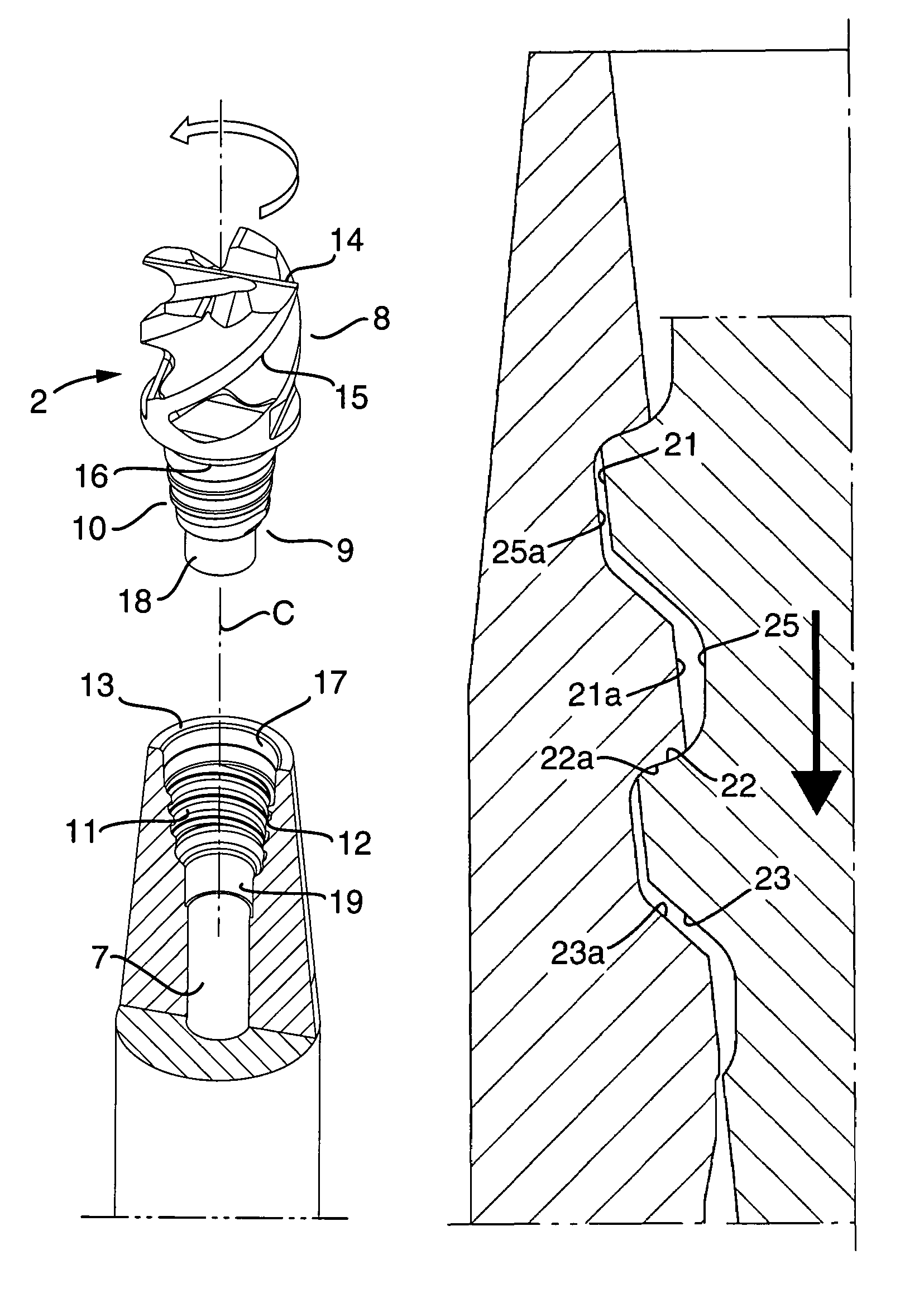
[0015]In accordance with a further aspect of an embodiment of the invention, there are formed two co-operating thread ridges of a threaded joint with different flanks. In particular, the first flanks of the respective ridges, which act pullingly in connection with screwing-in, are given a flank angle that is smaller than the flank angles of the second flanks, which act pressingly in connection with unscrewing. In such a way, the individual thread ridge obtains a proportion-wise greater amount of material (extra material) in the area inside the pressing flank, i.e., the thread ridge is reinforced in the area of the pressing flank. Accordingly, the resulting tensile-force applied to the thread ridge upon screwing-in is absorbed and distributed in the reinforcing extra material. An advantageous consequence is that larger tensile forces than compressive forces can be applied to the threaded joint while avoiding damage to the thread ridges.

Problems solved by technology

In modern machine tools, the basic bodies are so expensive that they, for economical reasons, cannot be integrated with the cutting body, which is a wear part and therefore has a limited service life.
It is believed that insofar as loose-top tools have been the object of a large number of proposals for design solutions, is per se evidence of the design of the interface between the loose top and the basic body is a technical problem that is difficult to master.
Thus, consideration has to be given to a number of different difficulties, which are based not only on the circumstance that the loose top and the basic body are manufactured from different materials and in production units separated from each other, but also on the circumstance that the tools should operate under severe external conditions, such as strong heat release, the influence from large cutting forces, and the like.
However, in practice, the manufacture of the two tool parts requires too a high dimensional accuracy in order for a serial production to be at least economically realistic.

Method used


Image

  • Tool for chip removing machining as well as a part and threaded joint therefor
  • Tool for chip removing machining as well as a part and threaded joint therefor
  • Tool for chip removing machining as well as a part and threaded joint therefor

Examples


Embodiment Construction

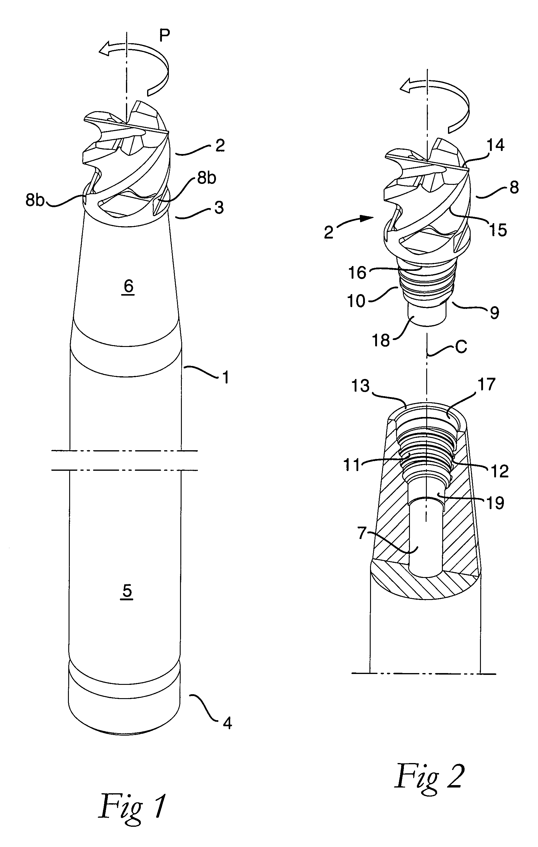
[0027]FIGS. 1 and 2 show a tool intended for chip removing machining of, for example, metallic work pieces. The tool includes two parts, e.g., a basic body 1 and a so-called loose top 2 in the form of a milling-cutter body, that are detachably connected to each other via a threaded joint. As shown, the basic body 1 has a long narrow shape and includes front and rear ends 3,4. The shape of the basic body 1 is characterized in that it is rotationally symmetrical, e.g., the outside of the basic body 1 includes a cylindrical surface 5 as well as a conical surface 6. The basic body 1 may be tubular by including a central through hole 7 (see FIG. 2), although the basic body may alternatively be solid.

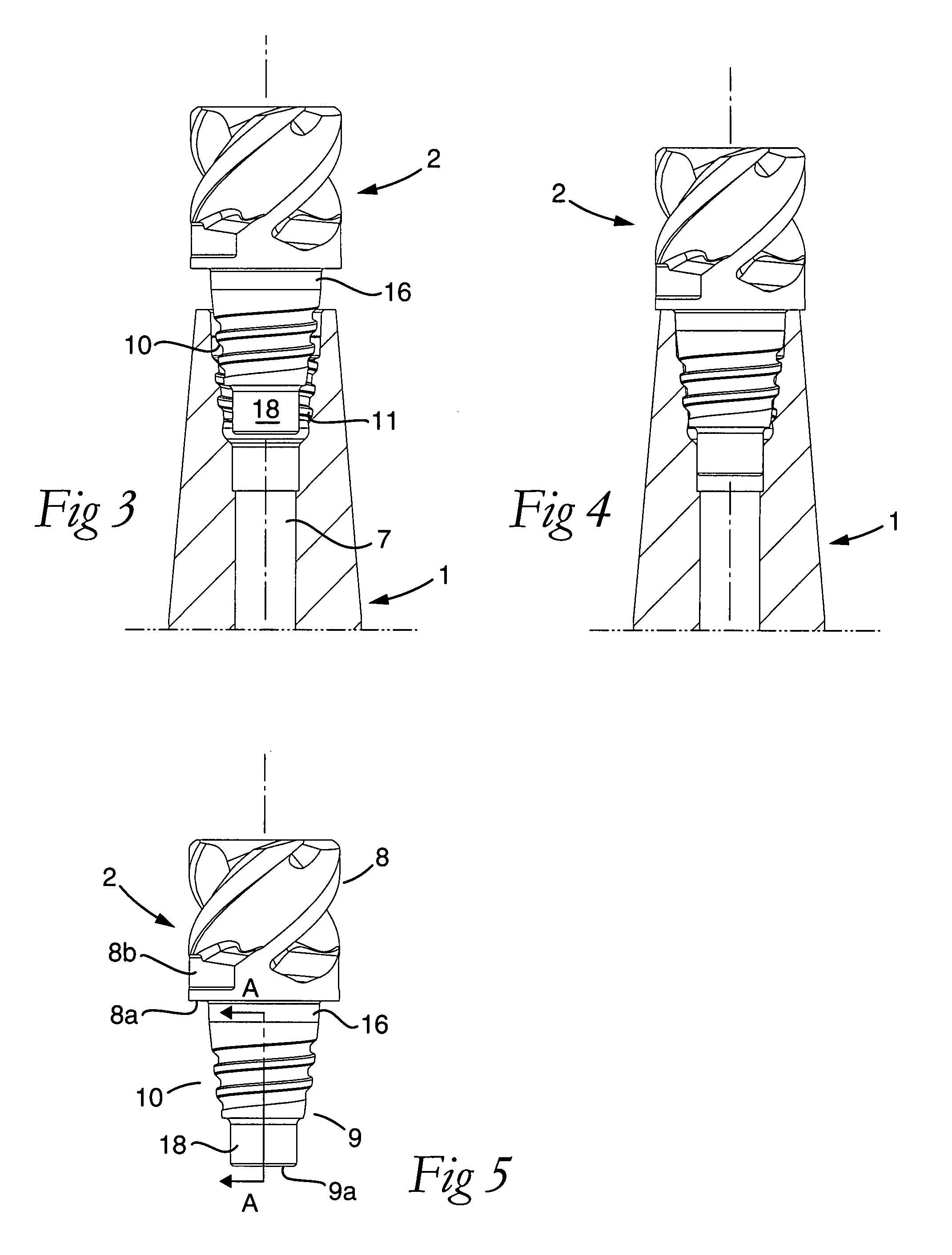
[0028]The loose top 2 includes a front head 8 and a rear pin 9. A male thread 10 is formed on the rear pin 9 and arranged to co-operate with a female thread 11 in a hollow space 12, which mouths in the front end 3 of the basic body 1. This mouth is surrounded by a ring-shaped shoulder surface...


PUM

PropertyMeasurementUnit
angleaaaaaaaaaa
angleaaaaaaaaaa
angleaaaaaaaaaa

Abstract

A cutting tool, and a loose top therefore, includes two parts detachably connected to each other via a threaded joint in which co-operating male and female threads are included in the form of helicoidal ridges. The profile shape of each helicoidal ridge is defined by a top and two flanks, which delimit a helicoidal groove having a bottom. The first flank is inclined in relation to a center axis of the tool at a first angle that is smaller than a second angle of the second flank in relation to the center axis. Accordingly, the thread ridge is reinforced in comparison with thread ridges having a symmetrical profile shape, whereby larger tensile forces than compressive forces can be applied to the threaded joint while avoiding damage to the thread ridges.

Description

CROSS-REFERENCE TO RELATED APPLICATIONS[0001]This application claims priority under 35 U.S.C. §119 to Sweden Application No. 0600875-9, filed on Apr. 20, 2006, the disclosure of which is incorporated by reference herein in its entirety.BACKGROUND OF THE INVENTION[0002]1. Field of the Invention[0003]In a first aspect, this invention relates to a tool intended for chip removing or cutting machining and of the type that includes two parts oriented along a common center axis and detachably connected to each other via a threaded joint. The threaded joint includes, on one hand, a female thread positioned in the vicinity of a mouth in a hollow space in one of the parts, and on the other hand a male thread positioned in the vicinity of a free end of a male-like pin included in the other part. The individual thread includes a helicoidal ridge, which has a top and a pair of opposite flanks, which delimit a likewise helicoidal groove having a bottom. A first flank of the male thread ridge, whi...

Claims


Application Information

Patent Timeline
Patent Type & Authority Patents(United States)
IPC IPC(8): B23C5/22B23B31/11B23B51/00
CPCB23B31/1107B23B51/00B23C5/10B23B31/1115Y10T408/907B23B2231/0204B23B2251/02B23C2210/02B23C2240/32Y10T408/95Y10T279/16Y10T408/90993Y10T407/1908Y10T407/1924Y10T407/1948B23B51/0004B23B27/16B23C5/22
Inventor KAKAI, ISAKLEHTO, RALFLARSSON, KENNETHORTLUND, MAGNUS
Owner SANDVIK INTELLECTUAL PROPERTY AB
Learn More