
Imaging system utilizing spatial image oscillation

a spatial image and image processing technology, applied in image acquisition, television systems, instruments, etc., can solve the problems of inherently inaccurate extraction of real-time velocity and noise-free detail from time-blurred frames of video, inability to avoid integrating noise into the detection process, and process resolution limitation by the number of pixels and their, so as to improve the image processing effect of imag

Inactive Publication Date: 2009-10-27
FOVIX CORP
View PDF9 Cites 12 Cited by
  • Summary
  • Abstract
  • Description
  • Claims
  • Application Information

AI Technical Summary

Benefits of technology

[0009]The present invention is directed to an imaging system and method utilizing spatial image oscillation to obtain enhanced image processing of an image.
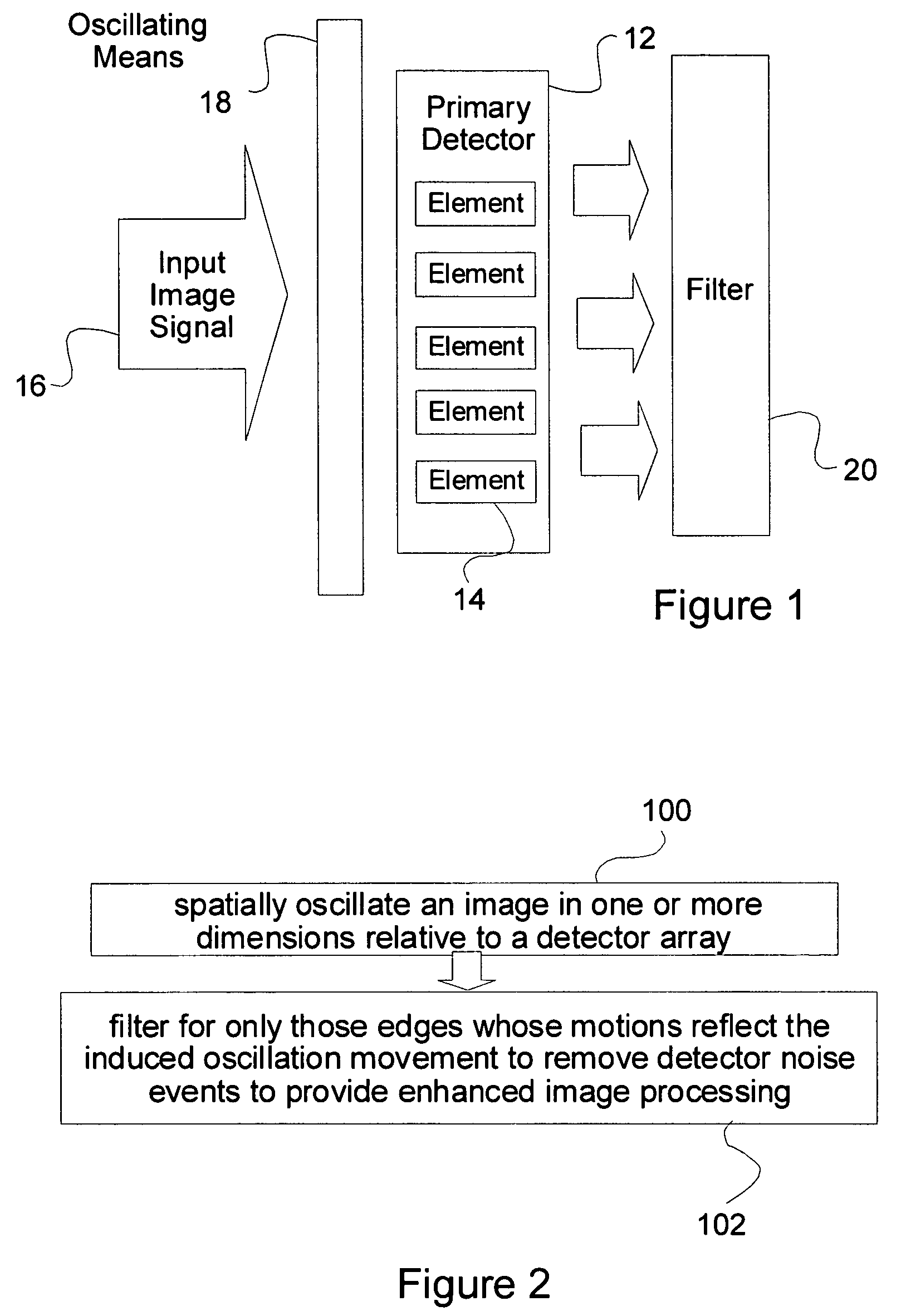
[0013]a spatio-temporally matching filter in communication with the image detector and the oscillation means for providing enhanced image processing of the image, the matching filter being configured to filter out aspects of the image signal not associated with the induced oscillation.
[0017]a spatio-temporally matching filter in communication with the image detector and the oscillation means, the matching filter being configured to filter for aspects of the image signal (eg. image edges) that are associated with the induced oscillation for providing enhanced image processing of the image.
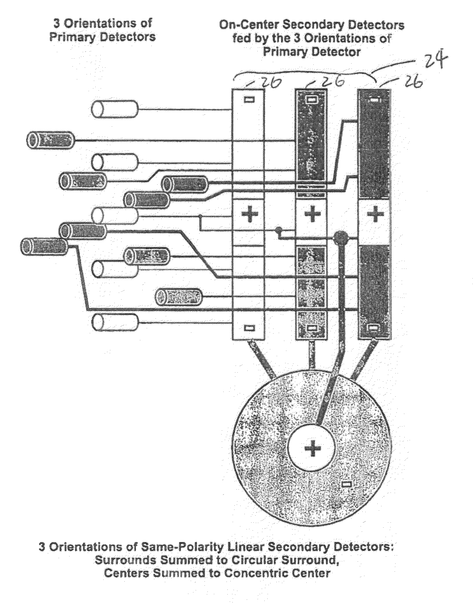
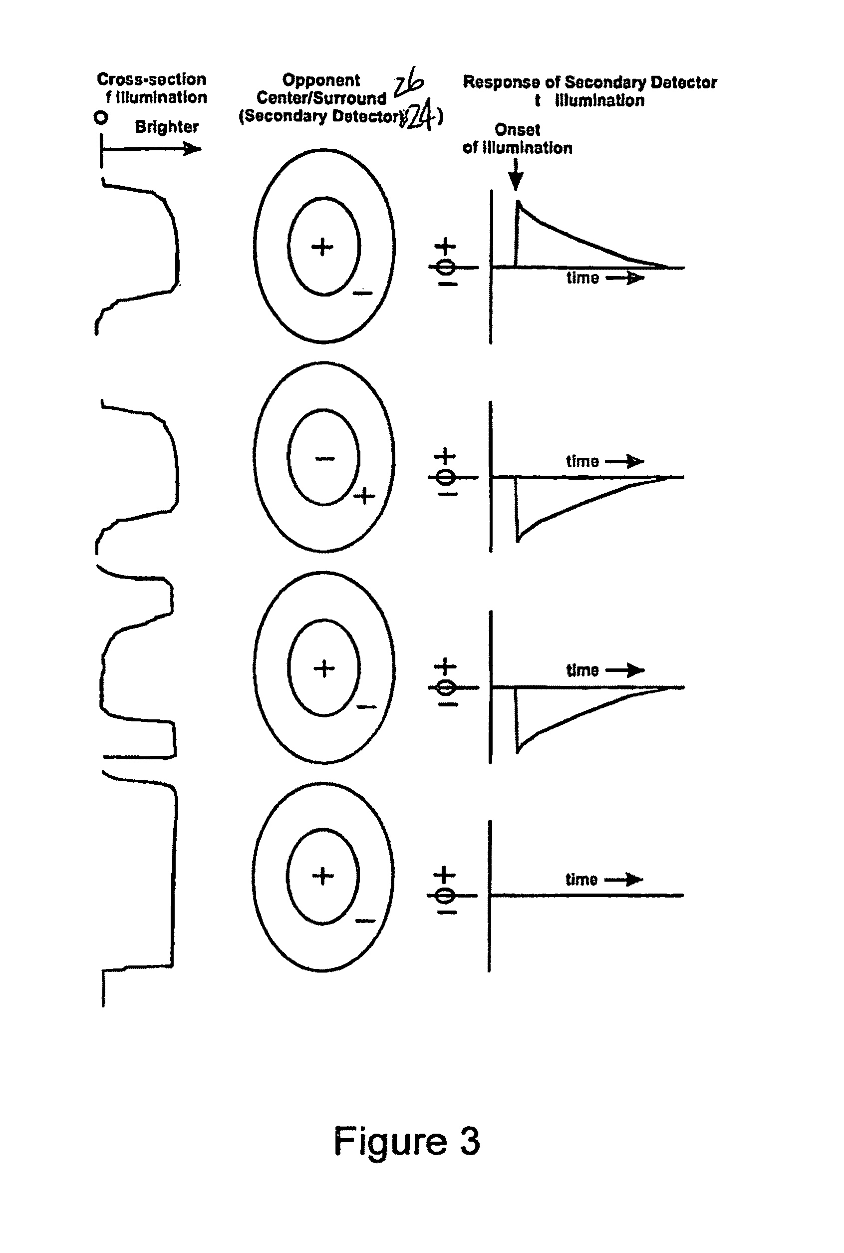
[0018]In one implementation, the system includes a secondary array of opponent center / surround detectors grouped by spatial orientation to provide multiple evenly-spaced orientations in the primary array for receiving signal inputs at the center / surround detector's center (interpreted as either positive or negative depending upon the polarity of opponent surround being passed the illumination information), and receiving opposing input from primary detectors adjacent to a primary central detector, each center / surround detector fed by one or more detectors from the primary detector array, therein extracting improved contrast, velocity, and relative luminance change information.
[0023]In one implementation, the spatial oscillation step is provided by a swept-frequency sinusoid chirp. Further, the method includes the step of receiving signal inputs at the center / surround detector's center (interpreted as either positive or negative depending upon the polarity of opponent surround being passed the illumination information), and receiving opposing input from primary detectors adjacent to a primary central detector, each center / surround detector fed by one or more detectors from the primary detector array, therein extracting improved contrast information to provide real-time spatial motion and velocity information.
[0024]The invention obtains a high-resolution, de-noised image and component velocities, directly from a lower-resolution detector feeding contrast / motion-sensitive opponent center surround detectors, by removing spatio-temporal noise, and correcting for pixel-to-pixel differences due to differences in detector responses, both in DC offset and gamma variations. As well, the invention greatly reduces downstream computational load for intelligent vision applications, and since this is applied at the detector level, if no active transmission, or illumination are involved, it can be purely passive, and therefore stealthy.

Problems solved by technology

The extraction of real-time velocity and noise-free detail from time-blurred frames of video has been inherently inaccurate.
The problem is that current image detection technology is based upon raster, frame-at-a-time, or arrays of independent pixels for scene capture using light (x-ray, ultraviolet, infrared or other medium) integrating pixels.
This process is limited in resolution by the number of pixels and their dimensions, and cannot avoid integrating noise into the detection process.
Since Gillette only calculates an estimate of the subpixel shifts, Gillette is unable to determine the portion of the magnitude of the pixel values actually attributable to the subpixel shifts.
This problem is compounded by the fact that Gillette averages the values of the pixels in successive frames that have the same estimated subpixel shift, thereby precluding removal of those aspects of the image frames not attributable to the subpixel shift.
Further, Gillette must estimate the subpixel shift in each frame, resulting in multiple frame delays for one high-resolution image.
Also, the frame basis of the method, and the corresponding finite exposure times, results in motion blur in each frame as objects traverse the scene.
Additionally, given the discrete sampling nature of the method, aliasing in time is possible if the sampling frequency is insufficient for the scene motion.
However, Ogmen only performs statistical neural filtering post-processing of the vision data, thereby integrating noise with the vision data, with the ultimate result of reduced signal detection.

Method used


Image

  • Imaging system utilizing spatial image oscillation
  • Imaging system utilizing spatial image oscillation
  • Imaging system utilizing spatial image oscillation

Examples


Embodiment Construction

[0035]The present invention is directed to a vision system, method and apparatus utilizing spatial oscillation. As illustrated in FIG. 1, the system includes a primary detector array 12 having detector elements 14 sensitive to an input image signal 16, means 18 for inducing a spatial oscillation in the image 16 relative to the primary detector array 12, and a filter 20 for filtering the image signal according to the spatio-temporal motion signature of the induced oscillation so as to extract those elements whose motions reflect the induced oscillation, therein removing noise events to provide enhanced image quality and simplified post-processing.

[0036]In an embodiment of the present invention, the induced oscillation means 18 is provided by a swept-frequency sinusoid chirp. In an embodiment of the present invention, the system further includes a secondary array 24 of opponent center / surround detectors 26 grouped by spatial orientation to provide multiple evenly-spaced orientations i...


PUM


Abstract

An imaging system includes an image detector for producing a continuous image signal from an image received thereat; oscillation means coupled to the image detector for inducing a spatial oscillation in the image relative to the image detector; and a spatio-temporally matching filter in communication with the image detector and the oscillation means. The matching filter is configured to filter out aspects of the image signal not associated with the induced oscillation, to thereby provide enhanced image processing of the image.

Description

RELATED APPLICATIONS[0001]This patent application is a continuation-in-part of International Patent Application PCT / CA02 / 00886, entitled “Vision System, Method and Apparatus Utilizing Spatial Oscillation”, filed Jun. 6, 2002, and claims the benefit of the filing date of Canadian Patent Application 2,349,828, entitled “Method, Apparatus, and System for Extracting Denoised, High-Resolution Images, Texture, and Velocity from a Lower-Resolution, Noisy Detector”, filed Jun. 6, 2001. International patent application PCT / CA02 / 00886 was published, in the English language, in publication document WO 02 / 099745 A2, on Dec. 12, 2002.FIELD OF THE INVENTION[0002]The present invention relates generally to imaging systems and methods, and more particularly to an electronic vision system that obtains high-resolution de-noised images and velocities from a lower-resolution detector.BACKGROUND OF THE INVENTION[0003]The extraction of real-time velocity and noise-free detail from time-blurred frames of v...

Claims


Application Information

Patent Timeline
IPC IPC(8): G03B13/00H04N5/232G06T1/00H04N5/217H04N5/349H04N5/357
CPCG06T1/0007H04N5/357H04N5/349H04N25/48H04N25/60H04N25/00
Inventor ZADOR, ANDREW
Owner FOVIX CORP
Learn More