
Comparator with low supply current spike and input offset cancellation

a technology of input offset cancellation and low supply current spike, which is applied in the direction of amplifiers, electrical devices, pulse manipulation, etc., can solve the problems of large current spikes of comparators on one or both voltage supplies, significant noise, and interference with chip operation

Active Publication Date: 2009-10-27
TOWER SEMICONDUCTOR
View PDF27 Cites 81 Cited by
  • Summary
  • Abstract
  • Description
  • Claims
  • Application Information

AI Technical Summary

Benefits of technology

The solution significantly reduces current spikes by maintaining a constant current draw, minimizing noise impact and avoiding the need for capacitors in the signal path, while allowing for replication in high accuracy applications like image sensor chips.

Problems solved by technology

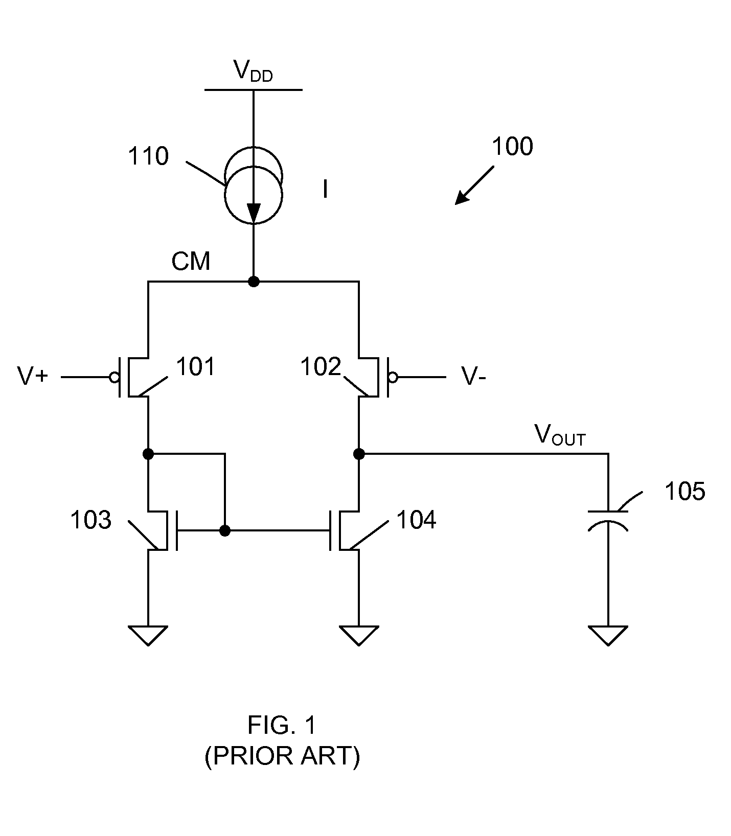
However, many known comparators have large current spikes on one or both voltage supplies during output transitions.
These current spikes can interfere with chip operation.
If the outputs of many comparators transition at the same time, large current spikes may exist on the VDD or ground rails, thereby creating significant noise that may adversely impact comparators having outputs that have not yet transitioned.
However, this amplifier stage undesirably exhibits a relatively low gain, requiring a large number of amplifier stages to be connected in series in order to provide an adequate gain.

Method used


Image

  • Comparator with low supply current spike and input offset cancellation
  • Comparator with low supply current spike and input offset cancellation
  • Comparator with low supply current spike and input offset cancellation

Examples


Embodiment Construction

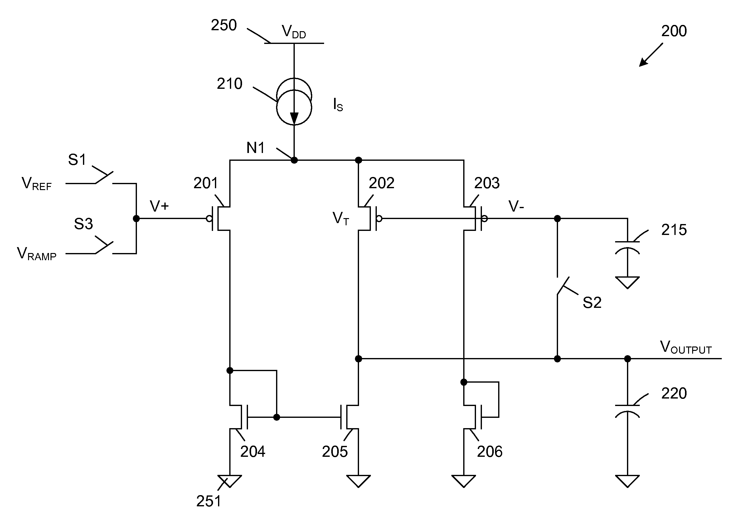
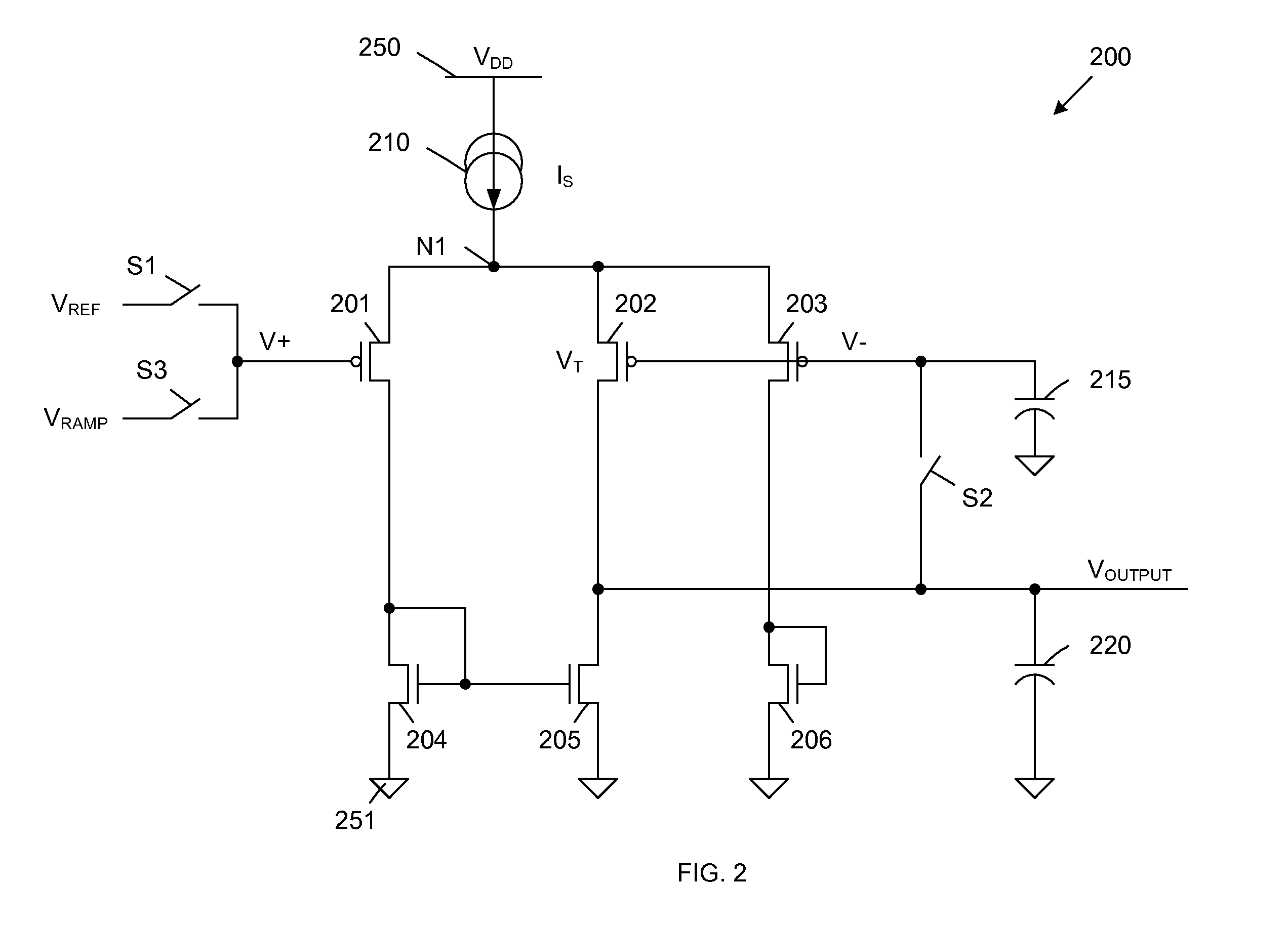
[0014]FIG. 2 is a circuit diagram of a comparator 200 in accordance with one embodiment of the present invention. Comparator 200 includes PMOS transistors 201-203, NMOS transistors 204-206, current source 210, sample capacitor 215, output capacitor 220 and switches S1-S3. Comparator 200 is supplied by a VDD voltage supply 250 and a ground voltage supply 251. These voltage supplies 250-251 effectively form a current source 210, which provides a source current (IS) to node N1.

[0015]As described in more detail below, PMOS transistors 201-202 and NMOS transistors 204-205 form a differential comparator circuit, which provides an output voltage (VOUTPUT) in response to the voltages (V+, V−) applied to the gates of PMOS transistors 201 and 202. PMOS transistor 203 and NMOS transistor 206 form a current control circuit, which is coupled in parallel with the current paths of the differential comparator circuit, and ensures that a substantially constant current is drawn from current source 21...


PUM


Abstract

A current control circuit is coupled in parallel with the current paths of a differential comparator circuit to ensure that a substantially constant current is drawn from a current source during all operating phases of a comparator. The current control circuit is biased by a reference voltage, which is also used to bias a V− input terminal of the differential comparator circuit. The reference voltage is stored by a sample capacitor, which is charged by applying the reference voltage to a V+ input terminal of the differential comparator circuit while coupling an output terminal of the differential comparator circuit to the sample capacitor in a unity feedback configuration.

Description

BACKGROUND OF THE INVENTION[0001]1. Field of the Invention[0002]The present invention relates to a comparator structure for use in high accuracy applications such as analog to digital converters (ADC).[0003]2. Related Art[0004]Comparators are often used in high accuracy applications, such as analog-to-digital conversion. In these applications, quiet high and low voltage supplies are required to achieve low supply noise. However, many known comparators have large current spikes on one or both voltage supplies during output transitions. These current spikes can interfere with chip operation. For example, an image sensor chip may include many column-parallel comparators, each having an output that switches when an input ramp signal reaches a reference level. If the outputs of many comparators transition at the same time, large current spikes may exist on the VDD or ground rails, thereby creating significant noise that may adversely impact comparators having outputs that have not yet tr...

Claims


Application Information

Patent Timeline
Patent Type & Authority Patents(United States)
IPC IPC(8): H03K5/22
CPCH03F3/45753H03K5/2481H03F2203/45212H03F2203/45396H03F2203/45354
Inventor SARIG, EREZRESHEF, RAZ
Owner TOWER SEMICONDUCTOR
Learn More