
Hall electromotive force signal detection circuit and current sensor thereof

a detection circuit and current sensor technology, applied in the direction of power supply testing, magnetic measurement, instruments, etc., can solve the problems of unbalanced voltage and offset voltage, and achieve the effect of reducing the occurrence of spike error signals, preventing the enhancement of hall electromotive force signal detection accuracy, and short tim

Active Publication Date: 2013-08-01
ASAHI KASEI ELECTRONICS CO LTD
View PDF12 Cites 28 Cited by
  • Summary
  • Abstract
  • Description
  • Claims
  • Application Information

AI Technical Summary

Benefits of technology

The present invention reduces the spike error signal that affects the accuracy of detecting Hall electromotive force signals. Additionally, it allows for high-accuracy offset cancellation that takes into consideration the influence of impurity concentration distribution in each Hall element. This results in a more efficient and accurate magnetic sensor, such as a current sensor, that requires fast responsiveness. The invention is also suitable for continuous-time signal processing circuits.

Problems solved by technology

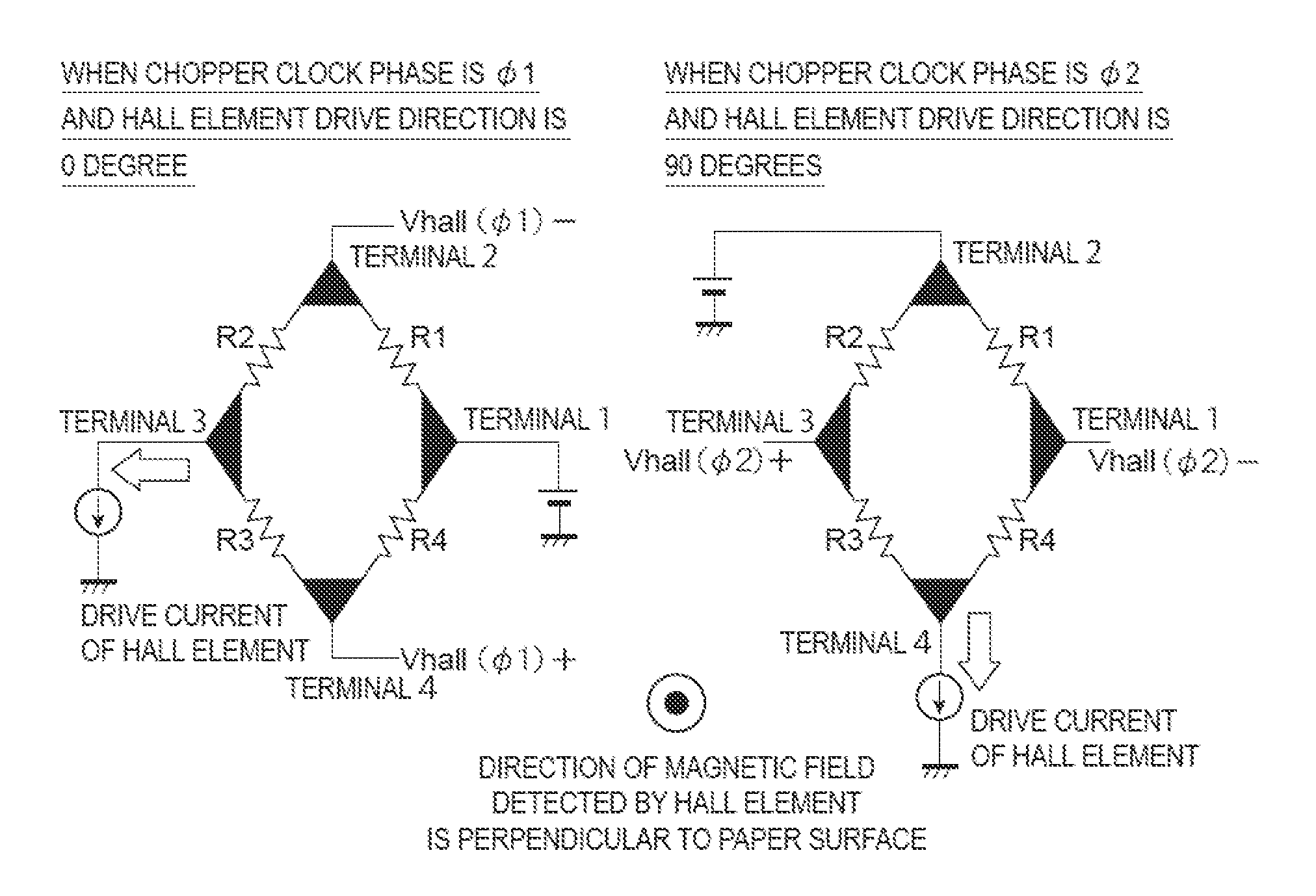
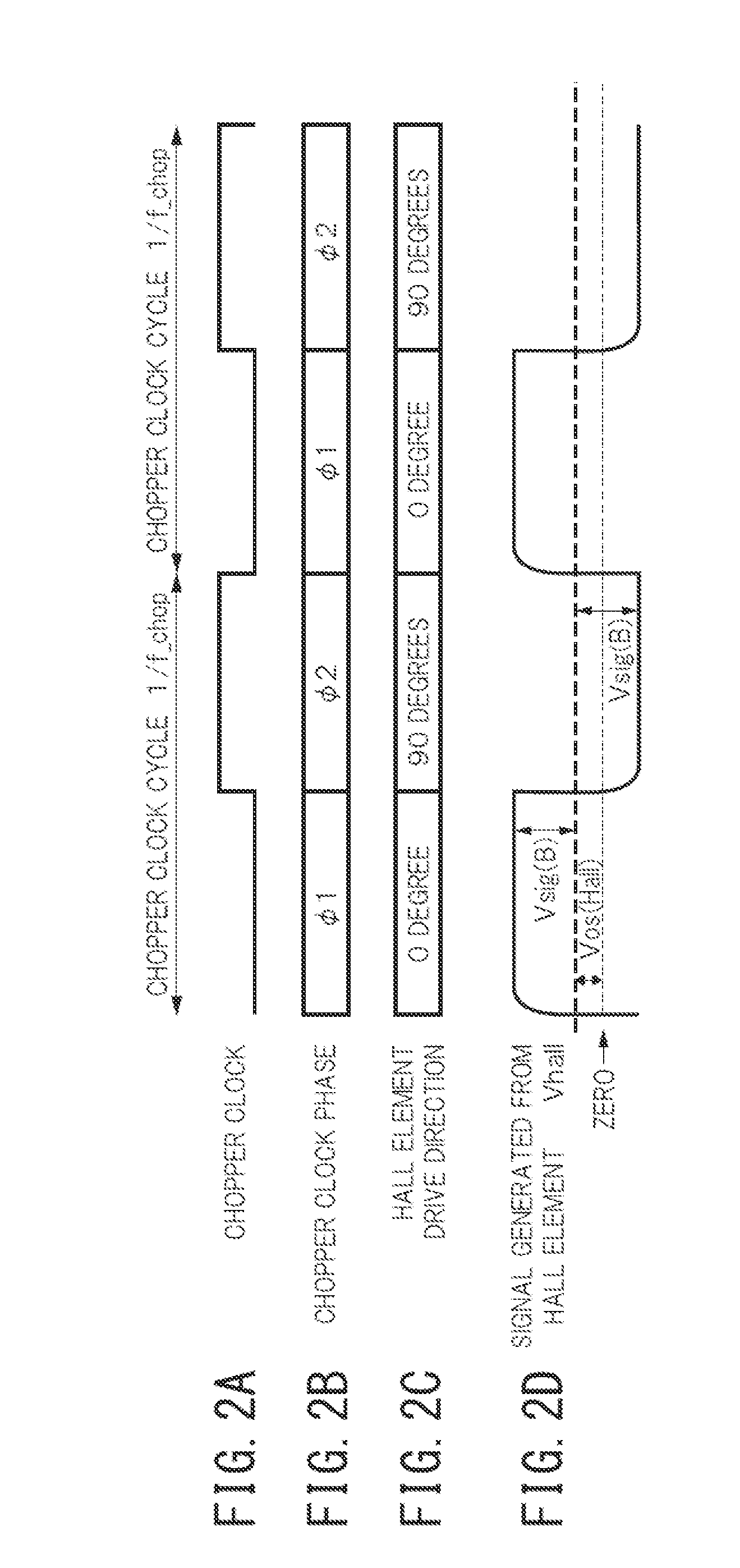
However, the Hall element has an offset voltage (unbalanced voltage) that is a finite nonzero voltage output even in a state where the magnetic field is zero, i.e. in a magnetic field-free state.

Method used


Image

  • Hall electromotive force signal detection circuit and current sensor thereof
  • Hall electromotive force signal detection circuit and current sensor thereof
  • Hall electromotive force signal detection circuit and current sensor thereof

Examples


Embodiment Construction

[0059]First, a structure of a Hall electromotive force signal detection circuit on which the present invention is premised will be described below, with reference to FIG. 4.

[0060]FIG. 4 is a circuit diagram illustrating a Hall electromotive force signal detection circuit on which the present invention is premised, and illustrates an example of a continuous-time signal processing circuit. In the drawing, reference sign 1 denotes a chopper clock generation circuit, 2 denotes a drive current generation circuit, 3 denotes a first Hall element, 4 denotes a first switching circuit, 5 denotes a second Hall element, 6 denotes a second switching circuit, and 7 denotes a Hall electromotive force signal addition circuit.

[0061]The Hall electromotive force signal detection circuit illustrated in FIG. 4 is a circuit in which Hall electromotive force signals Vhall 1 and Vhall2 generated respectively in the first Hall element 3 and the second Hall element 5 are simultaneously added in continuous ti...


PUM


Abstract

A Hall electromotive force signal detection circuit combines offset cancellation means by a spinning current method of a Hall element with a continuous-time signal processing circuit. A first Hall element includes first to fourth terminals, and generates a Hall electromotive force signal voltage Vhall1. A third Hall element generates an other Hall electromotive force signal voltage Vhall3. A first switching circuit selects a terminal position for applying a drive current from the four terminals of the first Hall element. A third switching circuit selects a terminal position for applying a drive current from the four terminals of the third Hall element, which is different from the terminal position selected by the first switching circuit. A chopper clock generation circuit supplies a chopper clock signal φ1, φ2 having two different phases to the switching circuit, and also supplies the chopper clock signal φ1, φ2 to the switching circuit.

Description

TECHNICAL FIELD[0001]The present invention relates to Hall electromotive force signal detection circuits and current sensors thereof.BACKGROUND ART[0002]A magnetic sensor using a Hall element is not only used in a proximity sensor, a linear position sensor, a rotation angle sensor, and the like as a sensor for detecting position information of a magnet, but also widely used in a current sensor for detecting a magnetic field induced by a current flowing through a current conductor to thereby contactlessly measure the current flowing through the current conductor.[0003]Particularly in a current sensor used to detect an inverter current of a motor, a current of an inverter switched at a high frequency needs to be detected with high accuracy, for the purpose of achieving efficient motor control.[0004]The Hall element has a magneto-electric conversion function of generating a Hall electromotive force signal corresponding to an intensity of an input magnetic field, and so is widely used a...

Claims


Application Information

Patent Timeline
Patent Type & Authority Applications(United States)
IPC IPC(8): G01R33/07
CPCG01R33/075G01R15/202G01R31/42
Inventor OKATAKE, SHIGEKINAKAMURA, TAKENOBUKATAOKA, MAKOTO
Owner ASAHI KASEI ELECTRONICS CO LTD
Learn More