
Process reactor with layered packed bed

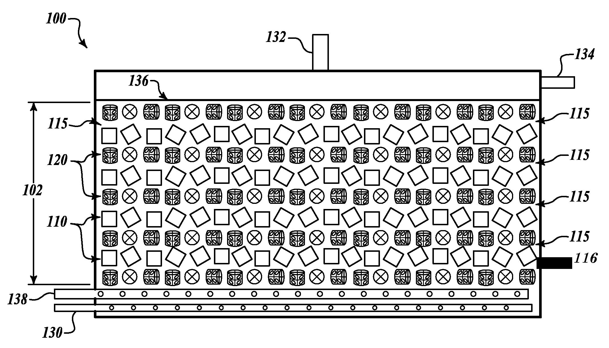
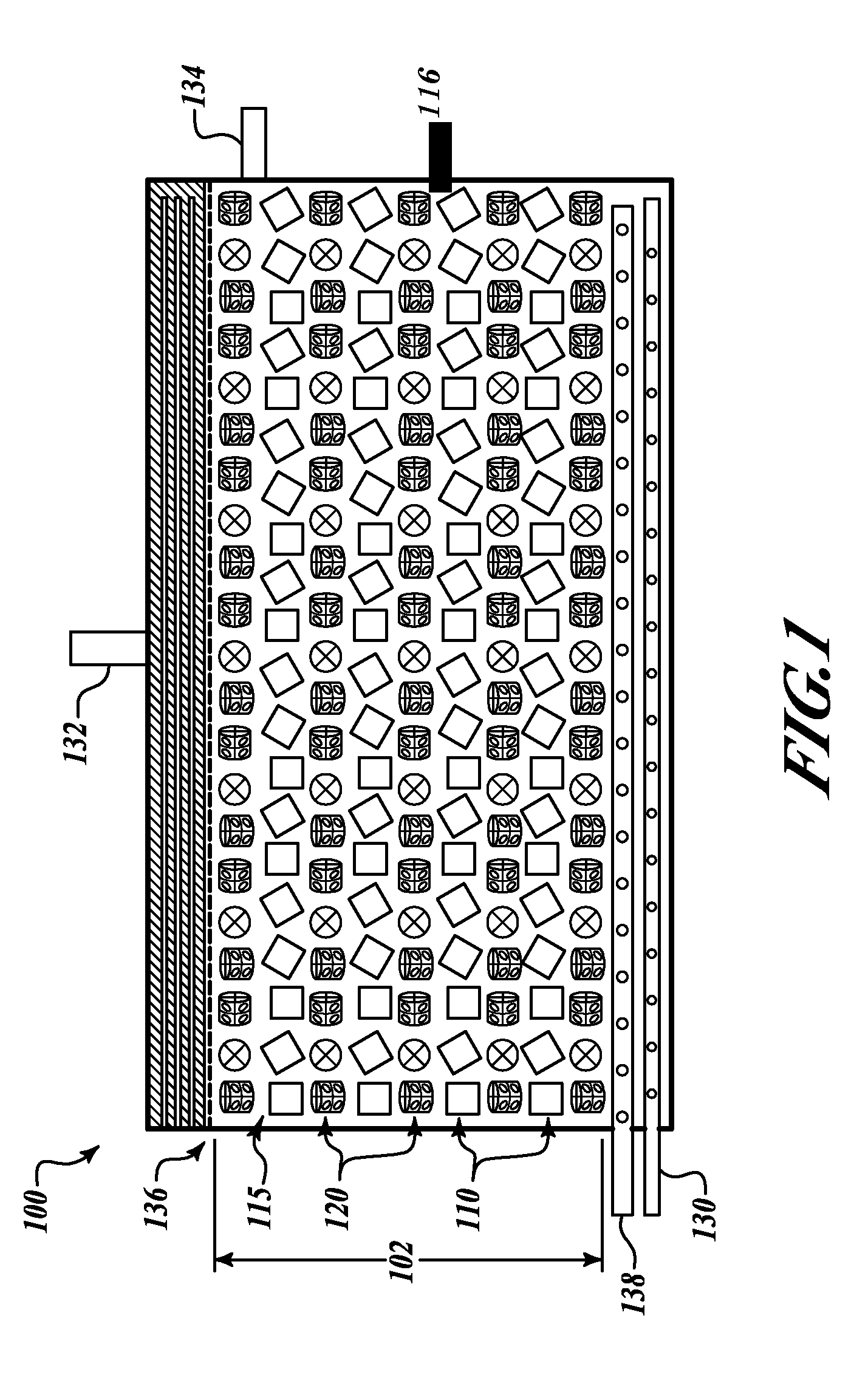
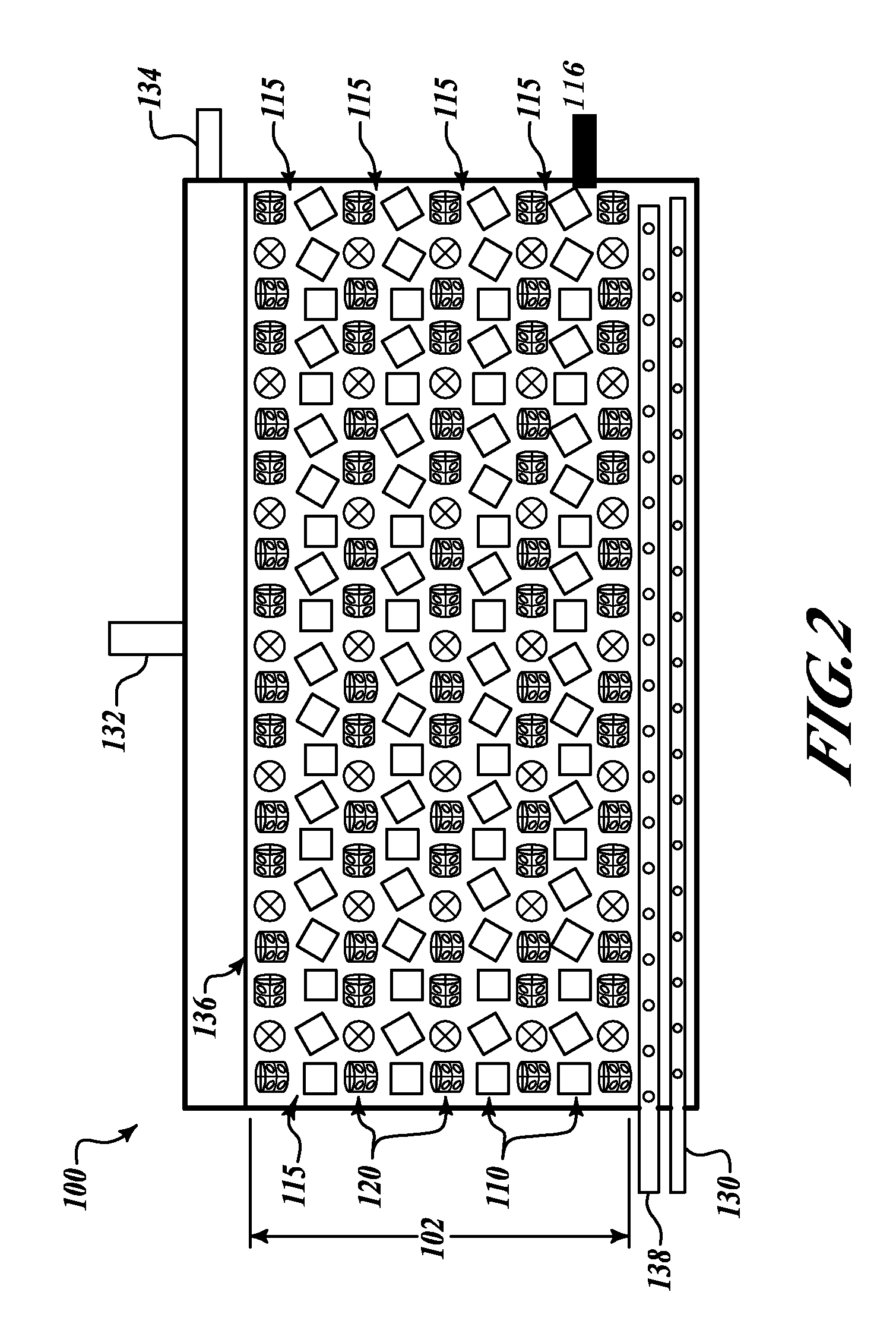
a reactor and layered technology, applied in the field of reactors, can solve the problems of poor fluid flow distribution and restrict the even distribution of biochemical reactants in the randomly packed bed, and achieve the effect of reducing the channeling through the bed and improving the residence time distribution of the reactor

Active Publication Date: 2009-09-01
UOP LLC
View PDF37 Cites 6 Cited by
  • Summary
  • Abstract
  • Description
  • Claims
  • Application Information

AI Technical Summary

Benefits of technology

This configuration results in improved pollutant removal rates, reduced sludge formation, and more consistent effluent quality, allowing for efficient treatment of pollutants to low parts-per-million levels within shorter residence times, while maintaining low pressure drop characteristics and minimizing channeling.

Problems solved by technology

Channeling, or poor fluid flow distribution, arises because air and water tend to find channels of least resistance through the random packing elements and biomass.
Further because growth of microorganisms is encouraged in zones adjacent to the channels, this further restricts the even distribution of these biochemical reactants throughout the randomly packed bed.

Method used


Image

  • Process reactor with layered packed bed
  • Process reactor with layered packed bed
  • Process reactor with layered packed bed

Examples


examples

[0090]A series of experiments were carried out to evaluate the effect of the orientation of open body spacers with the porous biomass supports, i.e. polyurethane foam.

example i

[0091]Rigid open cylinders (plastic) were obtained from Jaeger Products, Inc., under a trade designation of HiFlow. These open cylinders were used as open body packing elements in biodegradation experiments. The biologically active bodies were of hydrophobic polyurethane foam (PUF) obtained from Foamex, Inc., under a trade designation SIF II. This foam had a polyol content of 75% by weight (approximately 40% by weight ethylene oxide and 60% by weight propylene oxide) and a toluene diisocyanate content of approximately 25 to 35% by weight of reactants. The foam had 15-20 pores per inch, and pores were of varying sizes.

[0092]FIG. 5 illustrates three reactor configurations that were used. PUF porous biomass supports 110 and HiFlow open body packing elements 120 were mixed together in different proportions in order to achieve a certain amount of openness or void space in each bioreactor system. Each bioreactor was of the same volume (1 liter) and each reactor had the same quantity of op...

example ii

[0101]Another set of waste water treatment bioremediation studies were performed to compare the bulk removal efficiency of a randomly dispersed system of open body packing elements and porous biomass supports in a control with a reactor bed according to an embodiment of the invention that has alternating layers of the same supports and packing elements.

[0102]As shown in FIG. 6, four reactors were used, arranged in pairs. Each pair 60, 61 comprised two reactors 100, 101 linked in series so that effluent from the first reactor 100 was the feed stream to the next reactor 101. Using the procedure of Example I, the Total Organic Carbon (TOC) removal efficiencies for each of the systems were determined. The control pair of reactors, two 1-liter reactors 100, 101 linked in series, was filled with 0.5 inch HiFlow packing 120 and 0.5 inch SIF II foam blocks 110 randomly dispersed, while the other set 61 was filled with the packing arranged in alternative layers of HiFlow 120 and PUF blocks 1...


PUM

PropertyMeasurementUnit
hydraulic residence timeaaaaaaaaaa
residence timesaaaaaaaaaa

Abstract

Packed bed reactors that have a series of alternating layers of packing. A first packing layer has open body packing elements randomly packed in a layer up to about 10 packing elements deep; and a second packing layer has porous support elements of hydrophobic foam. The porous support elements are randomly packed up to about 10 porous support elements deep. Further, the packing elements of the first layer include substantially cylindrical shapes and the porous support elements of the second layer include substantially rectilinear shapes. In some embodiments, the second layer supports microbial organisms in a biological reactor, and the first layer of open body packing provides fluid flow spaces to facilitate fluid flow and distribution, mass transfer, and to minimize channeling.

Description

CROSS-REFERENCE TO RELATED APPLICATION(S)[0001]This application claims the benefit of priority from U.S. provisional patent application Ser. No. 60 / 698,106, filed Jul. 11, 2005.TECHNICAL FIELD[0002]The present invention relates generally to reactors. More particularly, the present invention relates to packed bed reactors suitable for use in chemical and biological processes.BACKGROUND[0003]Packed reactors are commonly used in the chemical, pharmaceutical, waste treatment, and fermentation industries for a variety of processes. In general, packing provides an increase in surface area inside the reactor, based on the surface area to volume ratio of the particular packing selected. Generally, the surface area of the packing provides a surface onto which reaction promoters such as microbes may attach in biological reactors, or onto which reaction promoters such as chemical catalysts may be attached in chemical reactors. Since the reaction process whether biological or chemical is genera...

Claims


Application Information

Patent Timeline
Patent Type & Authority Patents(United States)
IPC IPC(8): C12M1/14
CPCB01D53/85B01J19/30C02F3/101C02F3/06C02F3/10B01J2219/30223B01J2219/30246B01J2219/30257B01J2219/30276B01J2219/30433B01J2219/30466B01J2219/3085B01J2219/315B01J2219/30416Y02A50/20Y02W10/10
Inventor LUPTON, FRANCIS S.
Owner UOP LLC
Learn More