Controlling tar by quenching cracked effluent from a liquid fed gas cracker

a gas cracker and effluent technology, applied in the cracking process of hydrocarbon oil, chemical refining of tar, light and heating equipment, etc., can solve the problems of low yield, limited tle fouling on the process side, and lack of flexibility to crack heavier feedstocks

Active Publication Date: 2009-09-01
EXXONMOBIL CHEM PAT INC
View PDF8 Cites 2 Cited by
  • Summary
  • Abstract
  • Description
  • Claims
  • Application Information

AI Technical Summary

Problems solved by technology

Tar is a high-boiling point, viscous, reactive material that can foul equipment under certain conditions.
Olefin gas cracker systems are normally designed to crack ethane, propane and on occasion butane, but typically lack the flexibility to crack heavier feedstocks, such as liquids particularly those feedstocks that produce tar in amounts greater than one percent.
TLE fouling on the process side is very limited with gas feeds, since the tar yields are very low.
Even in the case of cracking ethane feed, the tar yield is high enough to cause the water leaving the quench drum to contain enough light tar, which has a specific gravity close to that of water, to cause downstream fouling of the quench circuit.
This can result in the fouling of downstream heat exchangers and water stripping towers, which, when fouled, must be taken offline for cleaning.
However, steam cracking economics sometimes favor cracking lower cost feedstocks containing resids such as, by way of non-limiting examples, atmospheric residue, e.g., atmospheric pipe still bottoms and crude oil.
Additionally, during transport, some naphthas or other lighter liquids are contaminated with heavy crude oil containing non-volatile components.
Conventional pyrolysis furnaces do not have the flexibility to process residues, crudes, or many residue or crude contaminated gas oils or naphthas which comprise non-volatile components.
Cracking heavier feeds, such as kerosenes and gas oils, may produce large amounts of tar, which can lead to rapid coking in the radiant section of the furnace as well as fouling in the transfer line exchangers preferred in lighter liquid cracking service, often requiring costly shutdowns for cleaning.
Furthermore, if a quench liquid such as water is used, the heavy oils and tars may form stable emulsions that make it difficult to dispose of excess quench water in an environmentally acceptable manner.
Neither of these techniques is, however, entirely optimum for use in steam crackers that crack liquefied petroleum gases, light naphthas, and ethane that produce relatively little heavy oil and tar.
One issue with these feedstocks stems from the fact that some of the heavy oils and tars produced when the pyrolysis effluent of these feedstocks is quenched have approximately the same density as water and can form stable oil / water emulsions.
Emulsion formation can render water quench operations ineffective, causing dilution steam generators to foul, and make disposal of excess quench water in an environmentally acceptable manner difficult.
Moreover, this further complicates the disposal of heavy oil and tar.
Such a system could, however, be more costly to construct and operate than a simple water quench system.
Additionally, the primary fractionator system may not generate sufficient heavy oil to allow it to replenish its own quench oil, some of which must be continuously removed to dispose of accumulated tars.
As such, operation of a primary fractionator under these conditions would require the added expense of an external supply of quench oil.
Furthermore, logistical difficulties are presented if the cracker is not located adjacent to a facility capable of providing quench oil and removing spent oil.
Steam crackers designed to operate on gaseous feedstocks, while limited in feedstock flexibility, require significantly lower investment when compared to liquid feed crackers designed for naphtha and / or heavy feedstocks that produce higher amounts of tar and byproducts.
However, as may be appreciated, when the price of natural gas is high relative to crude, gas cracking tends to be disadvantaged when compared with the cracking of virgin crudes and / or condensates, or the distilled liquid products from those feeds.

Method used


Image

  • Controlling tar by quenching cracked effluent from a liquid fed gas cracker
  • Controlling tar by quenching cracked effluent from a liquid fed gas cracker

Examples


Embodiment Construction

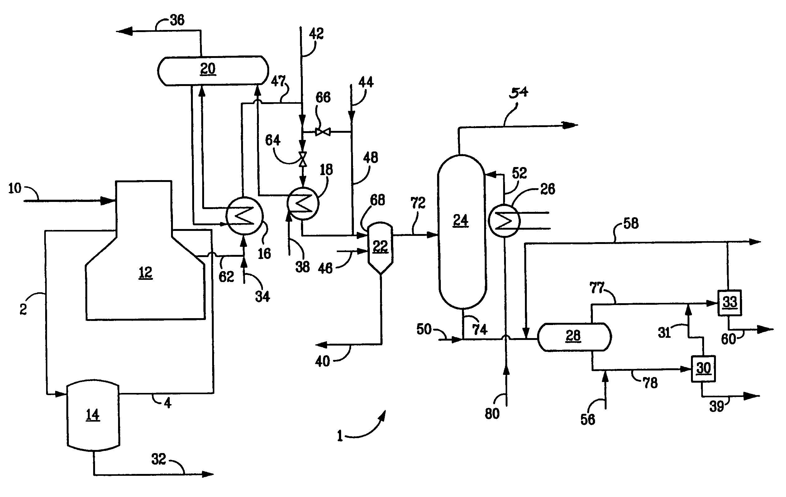
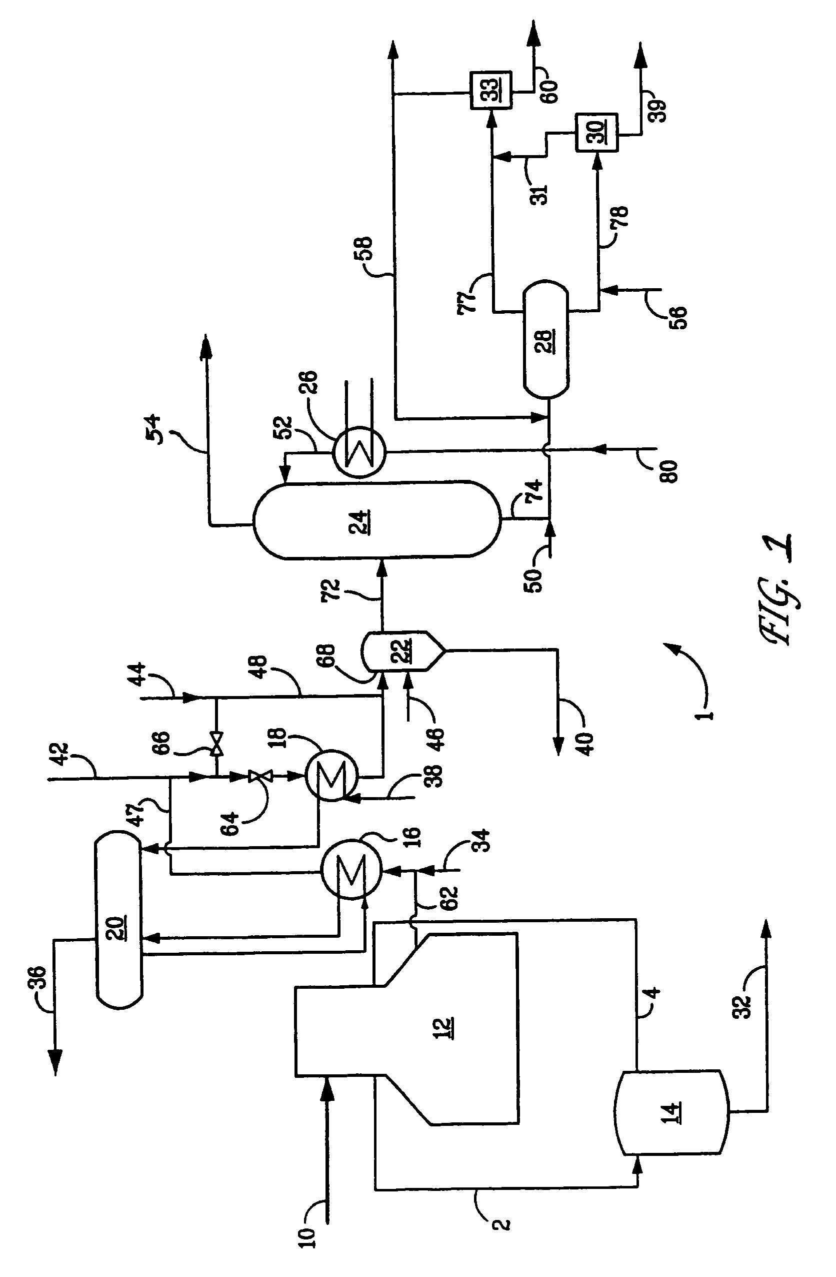
[0028]Various aspects will now be described with reference to specific embodiments selected for purposes of illustration. It will be appreciated that the spirit and scope of the process and system disclosed herein is not limited to the selected embodiments. Moreover, it is to be noted that the figure provided herein is not drawn to any particular proportion or scale, and that many variations can be made to the illustrated embodiments. Reference is now made to the figure, wherein like numerals are used to designate like parts throughout.

[0029]Disclosed herein is a process for extending the range of gas cracker system feedstocks to include liquid feedstocks, including feeds that yield tar, even for example, up to 15 wt % tar, after cracking. The process may extend gas cracker flexibility to crack virgin crudes, condensates and / or the distilled liquid products from those feeds, such as naphtha, kerosene, field natural gasoline, etc.

[0030]Liquid feedstocks that may be employed herein ma...


PUM

PropertyMeasurementUnit
boiling pointsaaaaaaaaaa
temperatureaaaaaaaaaa
boiling pointaaaaaaaaaa

Abstract

In a system for thermal cracking gaseous feedstocks, the system including a gas cracker for producing an effluent comprising olefins, at least one transfer line exchanger for the recovery of process energy from the effluent and a water quench tower system, a process for extending the range of system feedstocks to include liquid feedstocks that yield tar is provided. The process includes the steps of injecting a first quench fluid downstream of a primary transfer line exchanger to quench the process effluent comprising olefins, separating in a first separation vessel a cracked product and a first byproduct stream comprising tar from the quenched effluent, directing the separated cracked product to a water quench tower system and quenching the separated cracked product with a second quench fluid to produce a cracked gas effluent for recovery and a second byproduct stream comprising tar. An apparatus for carrying out such process is also provided.

Description

FIELD OF THE INVENTION[0001]The present invention relates to the cracking of hydrocarbons that contain relatively non-volatile hydrocarbons and other contaminants. More particularly, the present invention relates to extending the range of feedstocks available to a steam cracker.BACKGROUND OF THE INVENTION[0002]Steam cracking, also referred to as pyrolysis, has long been used to crack various hydrocarbon feedstocks into olefins, preferably light olefins such as ethylene, propylene, and butenes. Conventional steam cracking utilizes a pyrolysis furnace that has two main sections: a convection section and a radiant section. The hydrocarbon feedstock typically enters the convection section of the furnace as a liquid (except for light feedstocks which enter as a vapor) wherein it is typically heated and vaporized by indirect contact with hot flue gas from the radiant section and by direct contact with steam. The vaporized feedstock and steam mixture is then introduced into the radiant sec...

Claims


Application Information

Patent Timeline
Patent Type & Authority Patents(United States)
IPC IPC(8): C10C1/19C10G55/02F28D21/00
CPCC10G9/002
Inventor MCCOY, JAMES N.HAMMOND, BARRINGTON M.DUHON, DAVID J.ROONEY, MARK A.STRACK, ROBERT D.MESSINGER, JOHN R.
Owner EXXONMOBIL CHEM PAT INC
Why Eureka
Try Eureka