Wide temperature range uncooled transceiver module for uncontrolled environments

a transceiver module and wide temperature range technology, applied in lasers, laser cooling arrangements, laser details, etc., can solve the problems of large size and power consumption of optical transmitter packages, small tolerance for wavelength selection of dfb lasers, and increased heating costs, so as to improve heating efficiency

Inactive Publication Date: 2009-08-04
OPTICAL COMM PRODS
View PDF21 Cites 4 Cited by
  • Summary
  • Abstract
  • Description
  • Claims
  • Application Information

AI Technical Summary

Benefits of technology

[0008]In this regard, the present invention provides for a laser transmitter component within the optical transceiver that includes a small heating element. In accordance with the present invention a laser transmitter is provided that includes a heating element that is coup led to the laser package and is controlled to allow the laser to be heated to a higher temperature than the ambient temperature when low environmental temperature extremes occur. More particularly, the laser transmitter portion of the optical transceiver includes a semiconductor laser having an optimal operational temperature range, a laser driver circuit coupled to the semiconductor laser that provides a modulation current and a bias current to drive the semiconductor laser, a heating element thermally coup led to the semiconductor laser and a heating control circuit that monitors the bias current applied to the laser. The heating control circuit is programmed to look for drops in bias current, which are known to be indicative of drops in the surrounding ambient temperature. In response to a drop in bias current, the control circuitry energizes the heating element to provide heat to the semiconductor laser.
[0009]Key features of the laser transmitter component of the present invention include: the application of a heater directly to a laser utilized in an optical transceiver, such as CWDM transceivers; an improved heating efficiency that is achieved by wrapping the heater around the coaxial laser while leaving a substantial portion of the laser exposed; use of a flexible heater wrapped around the body of the coaxial laser; and the control of the heater responsive to changes in bias current readings from diagnostic monitoring of the laser.
[0010]Accordingly, it is an object of the present invention to provide a laser transmitter that includes a heater component, which in turn maintains the laser at an environmental temperature that optimizes the laser output performance. It is a further object of the present invention to provide a laser transmitter component that includes a high efficiency flexible heater wrapped around an exterior surface thereof to maintain the laser at an environmental temperature that optimizes the laser output performance. Finally, it is an object of the present invention to provide a laser that includes a high efficiency heater that is controlled using a feedback loop that monitors drops in the bias current applied to the laser and energizes the heater in response to those drops.

Problems solved by technology

The drawback to this packaging arrangement was that the size and power consumption of the optical transmitter package was greatly increased.
Even with the improvements in the laser diodes, however, there are still significant performance issues related to lasers that operate in cold environments thereby creating the need for heating.
The problem is that an uncooled distributed feedback (DFB) laser typically used in CWDM transceivers has a wavelength variation of 12.5 nm over the operational temperature range of between about −40° C. to 85° C. This 12.5 nm variation in laser wavelength leaves only a very small tolerance for the wavelength selection of the DFB laser.
Accordingly, there is less than a 0.5 nm window available for selection of the initial wavelength of the DFB laser, a window that simply cannot currently be achieved with consistent results.
For example, the pattern dependent turn-on delay increases significantly at low temperatures causing additional timing jitter.
In addition, mode partitioning in DFB lasers, which are designed to operate over a wide temperature range, increases at low temperatures possibly resulting in an excessive dispersion penalty for the entire system.

Method used


Image

  • Wide temperature range uncooled transceiver module for uncontrolled environments
  • Wide temperature range uncooled transceiver module for uncontrolled environments
  • Wide temperature range uncooled transceiver module for uncontrolled environments

Examples


Embodiment Construction

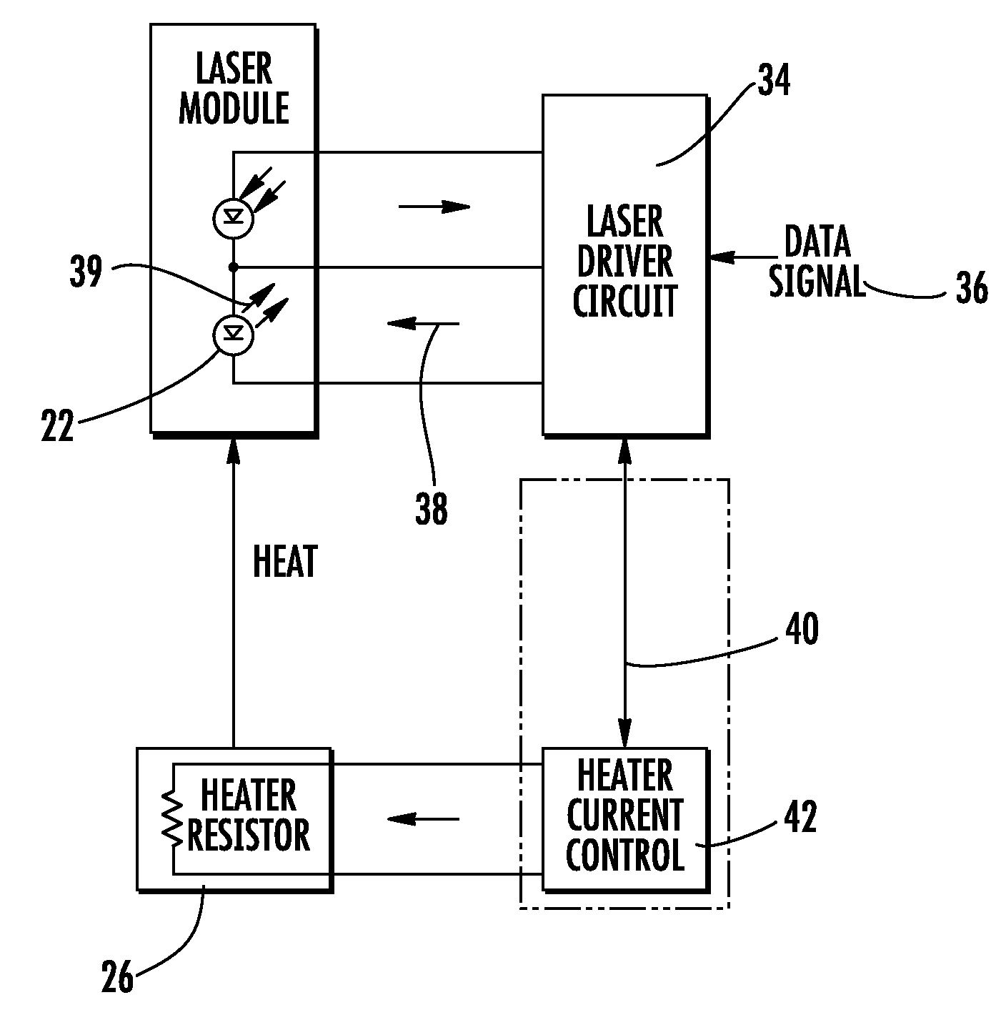
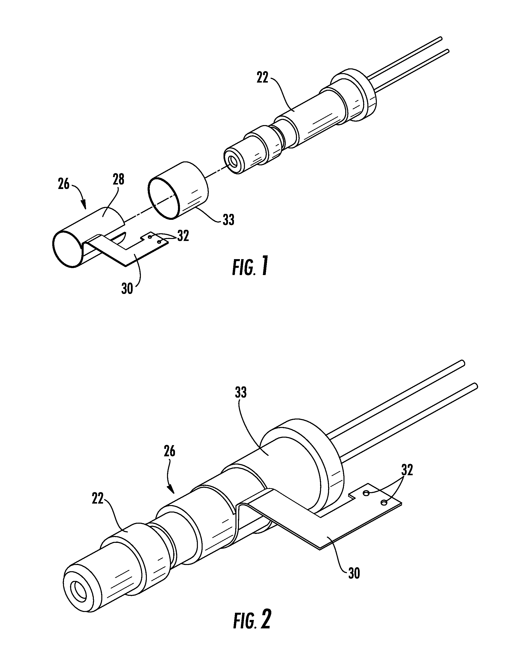
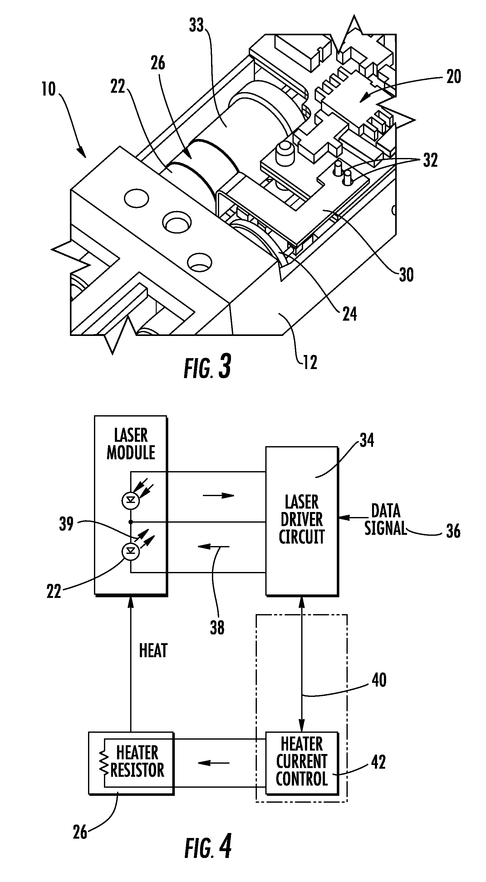
[0017]Now referring to the drawings, a pluggable optical transceiver module in accordance with the teachings of the present invention is illustrated and generally indicated at 10 in FIG. 3. The pluggable optical transceiver module 10 includes a housing generally indicated at 12. The transceiver module 10 shown in FIG. 3 is a transceiver capable of transmitting and receiving signals over a pair of coupled fiber optic transmission cables. The transceiver module 10 includes an optical subassembly generally indicated at 20 that includes an optical transmitter (TX) 22 in the form of a coaxial semiconductor laser and an optical receiver (RX) 24 such as a photodiode. The optical sub-assembly 20 shown in FIG. 3 is one example of a unit that can be installed in the optical transceiver module 10 of this invention and is shown for illustration purposes only. It is recognized that other optical subassembly units having different configurations can be installed in the optical transceiver 10 in a...


PUM


Abstract

A laser transmitter within an optical transceiver includes a heating element. The heating element is coup led to the laser package and is controlled to allow the laser to be heated to a higher temperature than the ambient temperature when low environmental temperature extremes occur. The transmitter includes a semiconductor laser having an optimal operational temperature range, a laser driver circuit coupled to the laser that provides a modulation current and a bias current to drive the laser, a heating element thermally coupled to the laser and a heating control circuit that monitors the bias current applied to the laser for drops in bias current that are indicative of drops in the surrounding ambient temperature. In response to a drop in bias current, the control circuitry energizes the heating element to provide heat to the laser.

Description

CROSS-REFERENCE TO RELATED APPLICATIONS[0001]This application is related to and claims priority from earlier filed U.S. Provisional Patent Application No. 60 / 743,334, filed Feb. 22, 2006, the contents of which are incorporated herein by reference.BACKGROUND OF THE INVENTION[0002]The present invention relates generally optical transceiver devices for use in uncontrolled environmental conditions. More particularly, the present invention relates to controlling the operating wavelength tolerances of a Coarse Wavelength Division Multiplexed (CWDM) transceiver in an uncontrolled environment that may have an environmental temperature range of between −40° C. to 85° C.[0003]It is known in the prior art that there is a need to maintain a laser device such, as an optical transmitter, at a relatively stable and constant temperature in order to optimize its performance characteristics and to maintain the output of the transmitter within a desired operational wavelength range. In this regard, se...

Claims


Application Information

Patent Timeline
Patent Type & Authority Patents(United States)
IPC IPC(8): H01S3/04
CPCH01S5/02212H01S5/02453H01S5/06837
Inventor GIBSON, PETERSTIMSON, MICHAEL
Owner OPTICAL COMM PRODS
Why Eureka
Try Eureka