
Tuning-fork type piezoelectric vibrating piece and oscillator

a piezoelectric and vibrating piece technology, applied in piezoelectric/electrostrictive/magnetostrictive devices, piezoelectric/electrostriction/magnetostriction machines, oscillators, etc., can solve the problems of short circuiting of remaining metal films and yield rate decline, and achieve high reliability, high reliability, and improved performance.

Inactive Publication Date: 2009-08-04
NIHON DEMPA KOGYO CO LTD
View PDF4 Cites 2 Cited by
  • Summary
  • Abstract
  • Description
  • Claims
  • Application Information

AI Technical Summary

Benefits of technology

The patent describes a tuning-fork type piezoelectric vibrating piece that prevents short circuits between electrodes near the bottom of the fork part. This is achieved by using a predetermined distance between the electrodes on the side surface of the arm unit and the bottom of the fork part. The distance between the electrodes affects the yield rate of the manufacturing process, and an optimal value is determined based on the equivalent series resistance value of the vibrating piece. The piezoelectric vibrating piece can be manufactured using a low-cost ceramic unit and can be surface mounted to a print board of electronics. Additionally, the patent describes a piezoelectric oscillator using the tuning-fork type piezoelectric vibrating piece and an amplifier circuit with a feedback circuit to determine the resonant frequency of the feedback loop. The invention provides a reliable and efficient tuning-fork type piezoelectric vibrating piece that prevents short circuits and improves performance.

Problems solved by technology

On the other hand, if the distance is short, a possibility of short circuiting by the remaining metal film is increased and the yield rate is decreased.

Method used


Image

  • Tuning-fork type piezoelectric vibrating piece and oscillator
  • Tuning-fork type piezoelectric vibrating piece and oscillator
  • Tuning-fork type piezoelectric vibrating piece and oscillator

Examples


Embodiment Construction

[0038]It is to be understood that the embodiments disclosed herein are not limited in application to the details of construction and the arrangement of components set forth in the following description or illustrated in the drawings. The disclosure is capable of other embodiments and of being practiced or being carried out in various ways. Also, it is to be understood that the phraseology and terminology used herein is for the purpose of description and should not be regarded as limiting.

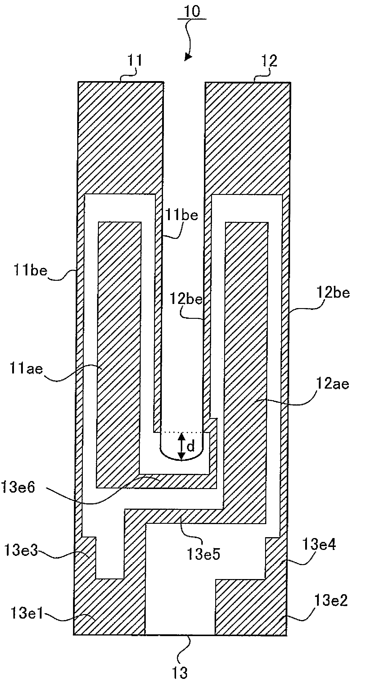
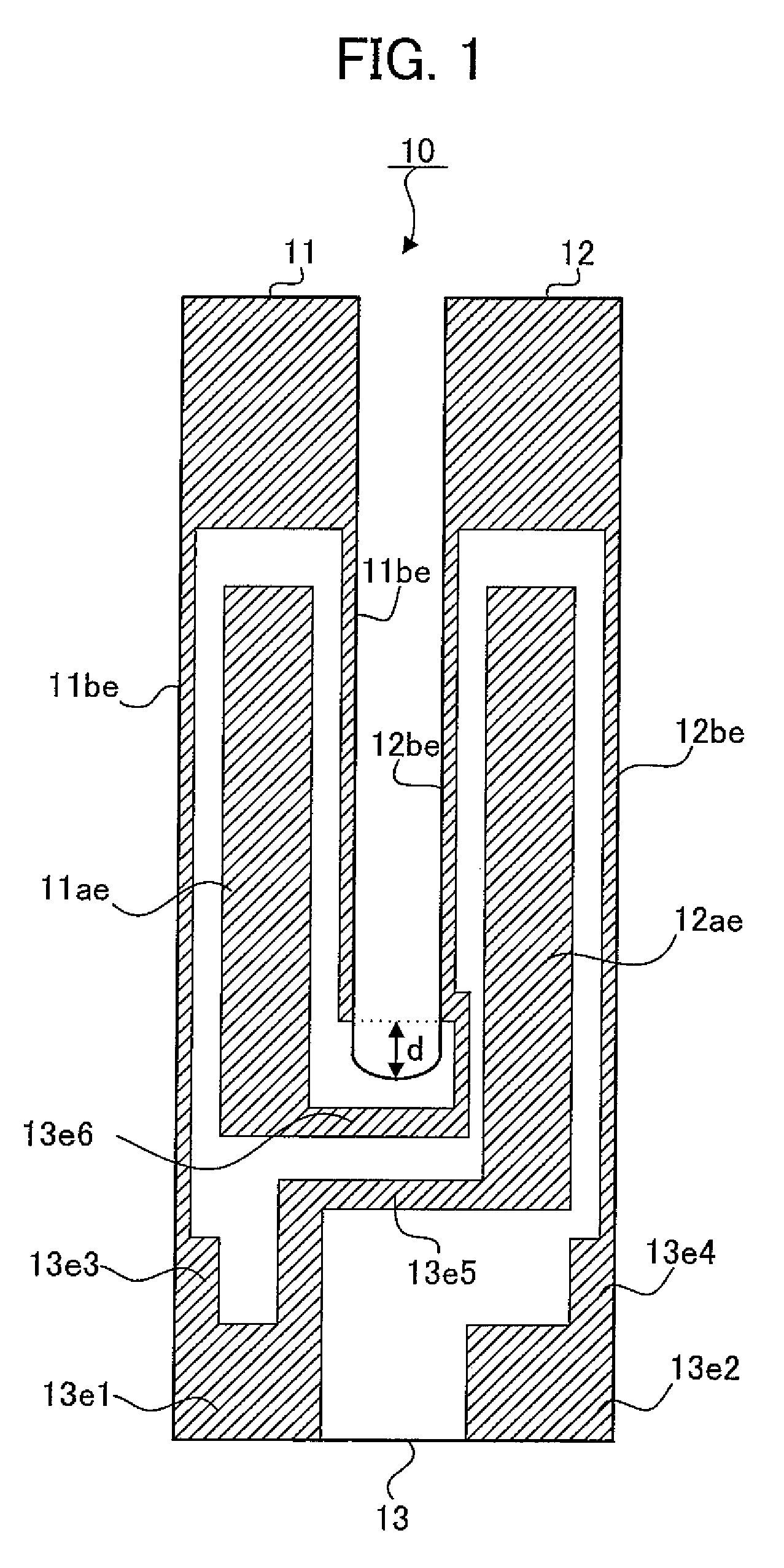
[0039]In one embodiment, FIG. 1 depicts an exemplary layout of the electrodes for the excitation and connections at the tuning-fork type piezoelectric vibrating piece 10. It should be noted that the tuning-fork type piezoelectric vibrating piece 10 depicted in FIG. 1 is similar to that explained in FIG. 6 above, and the perspective view of the entire unit or the cross-sectional view of the arm unit is omitted. As shown, the tuning-fork type piezoelectric vibrating piece 10 in FIG. 1 is comprised of ...


PUM


Abstract

A tuning fork type piezoelectric vibrating piece, comprising: a base unit having a base electrode for an external connection; a fork shaped arm unit extending from the base unit; a groove portion at least on a surface or a rear surface of the arm unit; a groove electrode on the groove portion; a side surface electrode on the arm unit without the groove portion; a first electrode connecting the base unit and the side surface electrode or the groove electrode; a second electrode connecting the groove electrode and the side surface electrode; and a side surface electrode set at a predetermined distance from the bottom of the fork part of the base unit. The piezoelectric vibrating piece may be packaged with a base electrode connected to an external output terminal. The piezoelectric oscillator may have an amplifier circuit and a feedback circuit with a resonant element determining the resonant frequency.

Description

CROSS-REFERENCE TO RELATED PATENT APPLICATION[0001]This application claims the benefit of Japanese Patent Application No. 2006-275193 filed on Oct. 6, 2006 in the Japan Patent Office, the disclosure of which is incorporated herein in its entirety by reference.FIELD OF THE INVENTION[0002]This invention is, for example, related to a tuning-fork type piezoelectric vibrating piece used with a crystal oscillator, a piezoelectric vibrating device used with an appropriate oscillator, and a piezoelectric oscillator used with an appropriate piezoelectric vibrating device.BACKGROUND[0003]Piezoelectricity has been used a number of useful applications. For example, crystal piezoelectric devices may be used for electronic frequency generation. With the increasing demand for miniaturization or weight savings in electronic devices, the tuning fork type crystal unit is becoming widely used. By forming the crystal unit to a tuning fork shape, the unit may produce low Crystal Impedance (CI) values. T...

Claims


Application Information

Patent Timeline
Patent Type & Authority Patents(United States)
IPC IPC(8): H01L41/047H03B5/32
CPCH03B5/32H03B5/36H03H3/04H03H9/1021H03H9/21H03H9/0547H03H2003/026
Inventor TAKAHASHI, TAKEHIRO
Owner NIHON DEMPA KOGYO CO LTD
Learn More