
Composite low cycle fatigue coiled tubing connector

a technology of coiled tubing and connectors, which is applied in the direction of sleeves/socket joints, drilling pipes, mechanical equipment, etc., can solve the problems of limited crane hoisting load capacity, prone to welding flaws, and significantly more complex logistics of orbital tig offshor

Inactive Publication Date: 2009-07-21
BAKER HUGHES HLDG LLC
View PDF39 Cites 7 Cited by
  • Summary
  • Abstract
  • Description
  • Claims
  • Application Information

AI Technical Summary

Benefits of technology

The connector achieves a cycle fatigue life of at least 30% to 50% of the coiled tubing life, exceeding previous designs, while ensuring superior corrosion resistance and axial loading capacity, and can be repeatedly spooled without failure, addressing the limitations of existing connectors.

Problems solved by technology

In particular, for offshore applications, the limitations on crane hoisting load capacities necessitates the assembly of two or more spools of coiled tubing once they have been delivered on deck.
It is also susceptible to welding flaws if the shielding gas became deflected from a crosswind.
In general, the logistics of performing orbital TIG offshore is significantly more complex.
However, the development of a mechanical connector that can be plastically spooled repetitively on and off a working reel, has not met with similar success.
The number of plastic bending cycles without failure of these mechanical connections was insufficient from both a practical, economic and safety point of view.

Method used


Image

  • Composite low cycle fatigue coiled tubing connector
  • Composite low cycle fatigue coiled tubing connector
  • Composite low cycle fatigue coiled tubing connector

Examples


examples

[0049]Low cycle fatigue life is determined using a CT Fatigue Testing Fixture, Broken Arrow Model, Ser. No. 002, bend fatigue-testing machine in Calgary, Alberta. Testing was performed at various bend radii typically 72 and 94 inches for the 2⅞ inches diameter coiled tubing used in offshore well interventions. A 7-foot long full sized CT specimen was used. The ends of the test specimen were sealed to enable an internal pressure to be applied with pressurized water while the specimen is subjected to cyclic bending from straight to curved and back to straight. This represented one (1) bend fatigue cycle and three (3) cycles corresponds to one (1) trip in and out of a well bore. Fatigue failure was obtained upon the loss of internal pressure that occurs immediately upon the formation of a crack or “pin hole” in the wall of the tubing. The actual allowable number of fatigue cycles (or equivalent trips) was obtained by dividing the cycle life to failure by a suitable factor of safety. Th...


PUM


Abstract

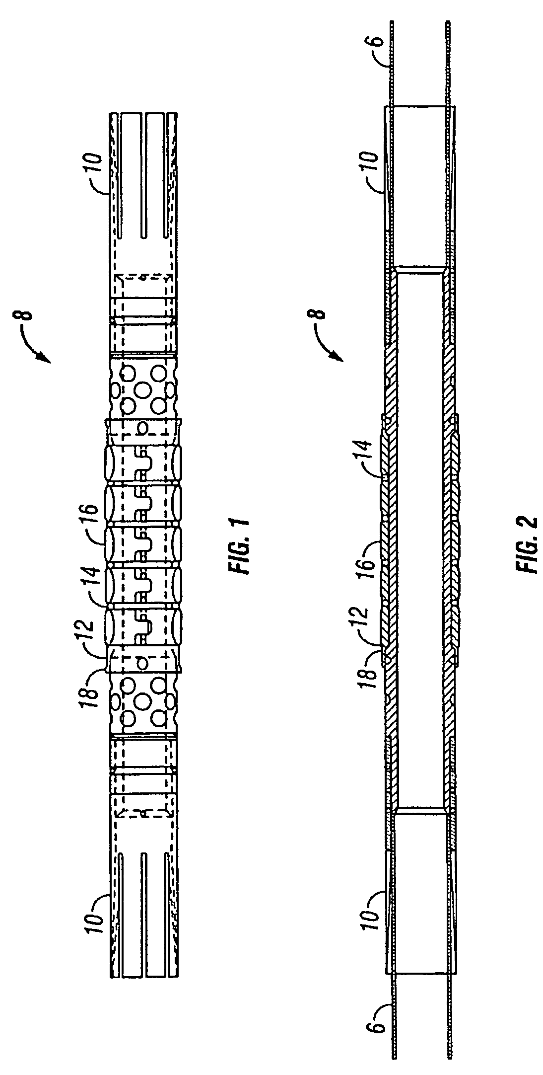
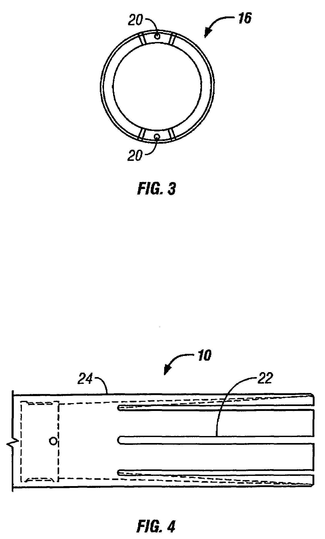
A coiled tubing connector having a body and a plurality of entry or transition sections connected to the body wherein the connector has a low cycle fatigue life of at least 30%, more preferably at least 50% of the coiled tubing. A preferred embodiment contains two shoulders that form an annular void, a plurality of centralizers about an exterior of the body, and / or a plurality of elastomer molds separating the centralizers. The connector is preferably longer than the connectors of the prior art and is a composite of fluoroplastics or aluminum alloys.

Description

CROSS REFERENCE TO RELATED APPLICATIONS[0001]The present application is a continuation application of U.S. patent application Ser. No. 10 / 394,392 filed Mar. 21, 2003 now abandoned.FIELD OF THE INVENTION[0002]The present invention relates to a tubing connector suitable for use with coiled tubing in oil and gas well operations.BACKGROUND OF THE INVENTION[0003]Coiled tubing is used in maintenance tasks on completed oil and gas wells and drilling of new wells. Operations with coiled tubing (“CT”) involving upstream oil and gas recovery requires the capability to make butt or girth joints in the tubing for a variety of reasons. In particular, for offshore applications, the limitations on crane hoisting load capacities necessitates the assembly of two or more spools of coiled tubing once they have been delivered on deck.[0004]There are two basic means to effect a girth joint connection. One way is by welding and the other involves the use of a spoolable mechanical connection. This may inc...

Claims


Application Information

Patent Timeline
Patent Type & Authority Patents(United States)
IPC IPC(8): F16L21/00E21B17/04E21B17/20
CPCE21B17/04E21B17/20Y10T403/57E21B17/041
Inventor LUFT, HANS-BERNDLAUN, LYLE ERWIN
Owner BAKER HUGHES HLDG LLC
Learn More