
Image pick-up lens, image pick-up unit, and mobile terminal provided with this image pick-up unit

a technology of image pick-up and mobile terminal, which is applied in the direction of color television details, television systems, instruments, etc., can solve the problem of not being able to reduce the size of the whole length of the image pick-up lens, and achieve the effect of appropriately maintaining lens performance and hardly generating image deterioration

Active Publication Date: 2008-09-02
KONICA MINOLTA OPTO
View PDF12 Cites 40 Cited by
  • Summary
  • Abstract
  • Description
  • Claims
  • Application Information

AI Technical Summary

Benefits of technology

[0008]Herein, in the present invention, relating to a scale for the small type image pick-up lens, a size reduction of a level to satisfy a following conditional expression, is aimed. When this range is satisfied, the whole length of the lens can be reduced, and geometrically the outer diameter of the lens can also be reduced. Thereby, the size and weight reduction of the whole image pick-up device become possible.L / 2Y<1.50  (7)Where, L: a distance on the optical axis from the object side surface of the first lens to the image side focal point of the whole image pick-up lens system,
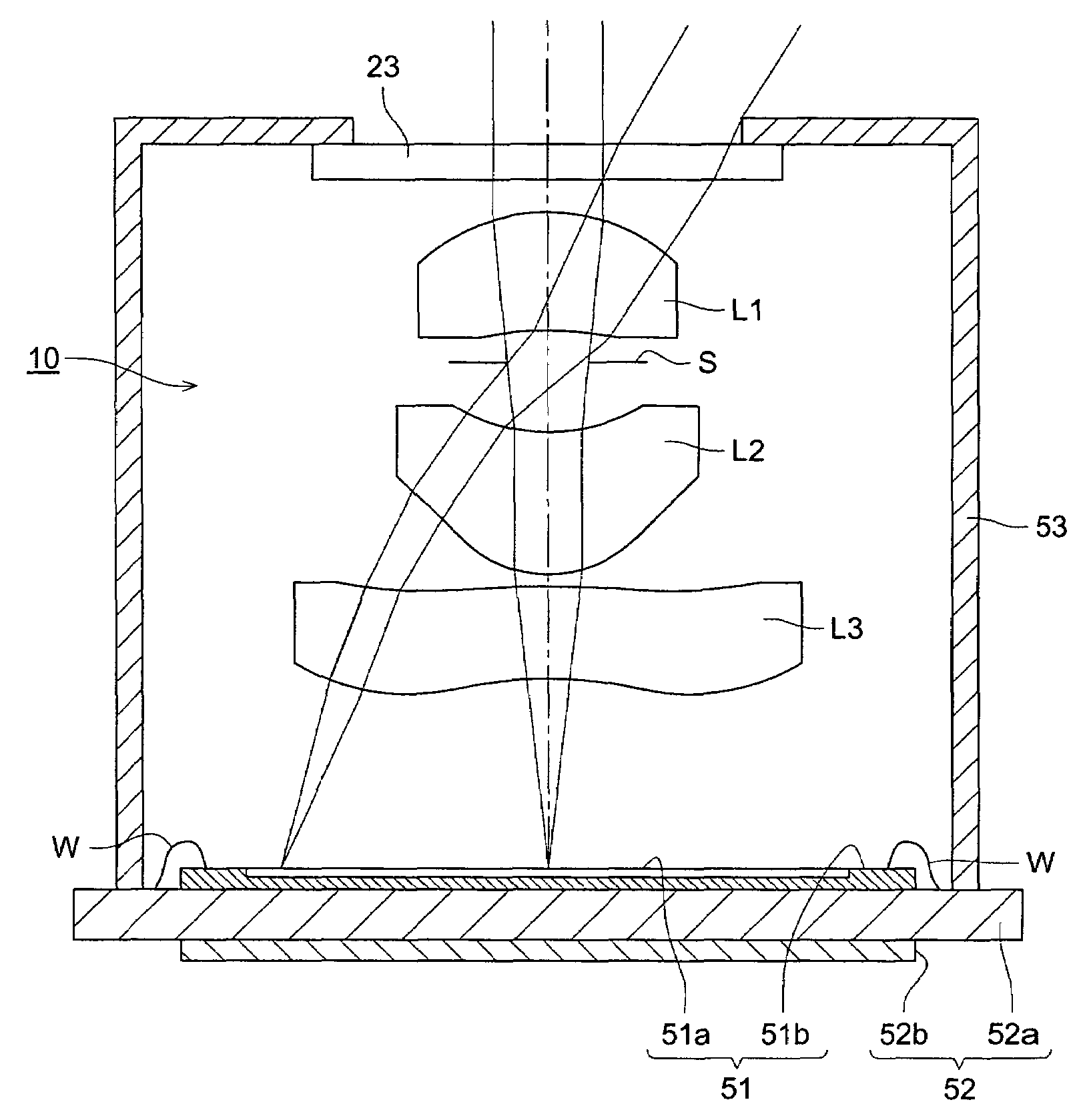
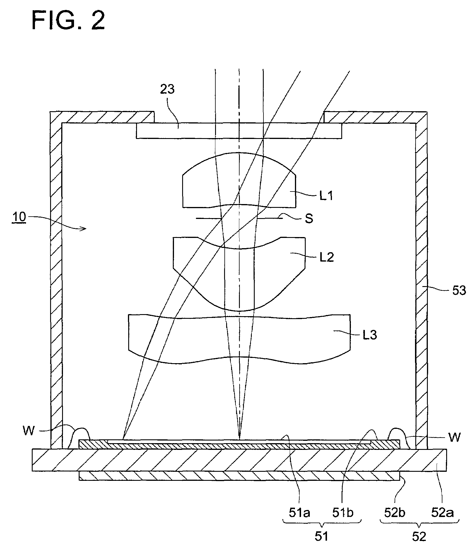
[0013]According to the structure written in item 1, because it is a so-called telephoto type lens construction in which, in order from the object side, the positive lens group composed of the first lens and the second lens and the third lens in which the concave surface is faced to the image side, are arranged, it is advantageous for the size reduction of the whole length, and the aberration can be finely corrected.
[0014]That is, for the aberration correction, because the positive refractive power is allotted by the first lens and the second lens, the generation of the spherical aberration or coma can be suppressed. Further, the aperture stop is arranged between the first lens and the second lens, and because the first lens has the shape in which the convex surface is faced to the object side, and the second lens has a meniscus shape in which the convex surface is faced to the image side, it is the structure in which the lateral chromatic aberration or distortion aberration is easily corrected.
[0015]Herein, the conditional expression (1) is an expression which regulates the refractive power of the first lens. When it is less than the upper limit value in the expression (1), the positive refractive power of the first lens can be appropriately maintained, and the size of the whole length of the image pick-up lens can be reduced. On the one hand, when it is upper than the lower limit value, the refractive power of the first lens is not too large than the necessary one, and the higher order spherical aberration or coma, which generates in the first lens, can be suppressed small. Further, more preferably, a value of f1 / f of the conditional expression (1) is within a range of the conditional expression of the following (9).0.8<f1 / f<1.65  (9)
[0017]Further, because the lens composition as described above is a composition which can secure a slightly large eccentricity allowance of each lens, for example, at the time of mass production, even when the optical axis of each lens is assembled in with a minute amount deviation from the same straight line, there is also the effect that the image deterioration hardly generates, and the lens performance can be appropriately maintained.

Problems solved by technology

However, although an image pick-up lens of a type which is written in Patent Document 1, is a type in which a wide image angle is secured and aberrations are finely corrected, on the one hand, it is not suitable for a size reduction of the whole length of the image pick-up lens (a distance from the most object side surface of the whole image pick-up lens system to the image side focal point).

Method used


Image

  • Image pick-up lens, image pick-up unit, and mobile terminal provided with this image pick-up unit
  • Image pick-up lens, image pick-up unit, and mobile terminal provided with this image pick-up unit
  • Image pick-up lens, image pick-up unit, and mobile terminal provided with this image pick-up unit

Examples


example 1

[0142]Next, the specification of the image pick-up lens will be described according to examples 1-5, however, each of specifications is not limited to this. Herein, the sign used for each example is as follows.[0143]f: Focal length of the whole image pick-up lens system[0144]fB: Back focus[0145]F: F-number[0146]2Y: Image pick-up surface diagonal length of solid-state imaging element[0147]R: Radius of curvature of a refractive surface[0148]D: On-axial surface interval of refractive surfaces[0149]Nd: Refractive index in d-line of lens material[0150]νd: Abbe's number of lens material

[0151]Further, in each example, the shape of aspheric surface is shown by the following expression expressed by the following (27), where an apex of the surface is the origin, and X axis is set in the optical axis direction, height in perpendicular direction to the optical axis is h, apex radius of curvature is R, conical constant is K, and i−order aspheric surface coefficient is Ai.

[0152]X=h2R1+1-(1+K)⁢h2 / ...

1st example

THE 1ST EXAMPLE

[0153]The image pick-up lens data is shown in Tables 1 and 2, and numerical value corresponding to each conditional expression is shown in Table 3.

[0154]

TABLE 1(Example 1)f = 3.81 mm, fB = 1.65 mm, F = 2.88, 2Y = 4.61 mmSurfaceNo.R (mm)D (mm)Ndνd11.8181.001.5318056.023.7130.25Stop∞0.623−1.6871.221.5318056.04−0.9000.1056.8000.781.5830030.061.534

[0155]

TABLE 2Aspheric surface coefficientThe 1st surfaceK = 9.15720 × 10⁻¹A4 = −3.85700 × 10⁻³A6 = 1.19250 × 10⁻³A8 = 1.54340 × 10⁻³A10 = −1.05850 × 10⁻³The 2nd surfaceK = 1.90040 × 10A4 = 1.42930 × 10⁻³A6 = 6.64670 × 10⁻²A8 = −1.05450 × 10⁻¹A10 = −2.10100 × 10⁻²The 3rd surfaceK = −1.94220 × 10⁻¹A4 = −2.56700 × 10⁻²A6 = −2.35200 × 10⁻¹A8 = 3.40250 × 10⁻¹A10 = −7.14810 × 10⁻²The 4th surfaceK = −2.82330A4 = −2.17930 × 10⁻¹A6 = 1.31190 × 10⁻¹A8 = −8.59110 × 10⁻²A10 = 2.63410 × 10⁻²A12 = 6.50500 × 10⁻⁴The 5th surfaceK = −9.76570 × 10A4 = −6.25440 × 10⁻²A6 = 3.00290 × 10⁻²A8 = −4.57290 × 10⁻³A10 = −2.41900 × 10⁻⁴A12 = 5.36600 × 10⁻⁵T...

example 2

[0158]The image pick-up lens data is shown in Tables 4 and 5, and numerical values corresponding to each conditional expression are shown in Table 6.

[0159]

TABLE 4(Example 2)f = 3.56 mm, fB = 1.48 mm, F = 2.88, 2Y = 4.61 mmSurfaceNo.R (mm)D (mm)Ndνd11.7110.901.5318056.029.2690.25Stop∞0.463−1.1670.981.5318056.04−0.7480.10526.8300.651.5830030.061.453

[0160]

TABLE 5Aspheric surface coefficientThe 1st surfaceK = 3.94660 × 10⁻¹A4 = −1.20790 × 10⁻²A6 = −1.20570 × 10⁻²A8 = 1.00970 × 10⁻²A10 = −1.31300 × 10⁻²A12 = −1.31310 × 10⁻³The 2nd surfaceK = −5.01610 × 10A4 = −2.11260 × 10⁻²A6 = −2.27930 × 10⁻³A8 = −8.49250 × 10⁻²A10 = 8.15610 × 10⁻²A12 = −2.06740 × 10⁻²The 3rd surfaceK = −1.16690 × 10⁻¹A4 = −8.99550 × 10⁻²A6 = −4.25790 × 10⁻¹A8 = 4.54500 × 10⁻¹A10 = −3.46760 × 10⁻²A12 = −1.95040 × 10⁻¹²The 4th surfaceK = −2.98890A4 = −3.2280 × 10⁻¹A6 = 2.52660 × 10⁻¹A8 = −1.94250 × 10⁻¹A10 = 7.76110 × 10⁻²A12 = 6.35480 × 10⁻³The 5th surfaceK = 1.00000 × 10²A4 = −8.85700 × 10⁻²A6 = 5.41380 × 10⁻²A8 = −1....


PUM


Abstract

An image pickup lens includes in order from an object side of the image pickup lens: a first lens having positive refractive power whose convex surface faces the object side of the image pickup lens; an aperture stop; a meniscus shaped second lens having positive refractive power whose convex surface faces an image side of the image pickup lens; and a third lens having negative refractive power whose concave surface faces the image side of the image pickup lens, wherein the image pickup lens satisfies the following conditional expressions:0.8<f1 / f<2.0  (1)20<((ν1+ν2) / 2)−ν3<70  (2)where f1 is a focal length of the first lens, f is a focal length of a total system of the image pickup lens, and ν1, ν2 and ν3 are the Abbe constants of the first to third lenses respectively.

Description

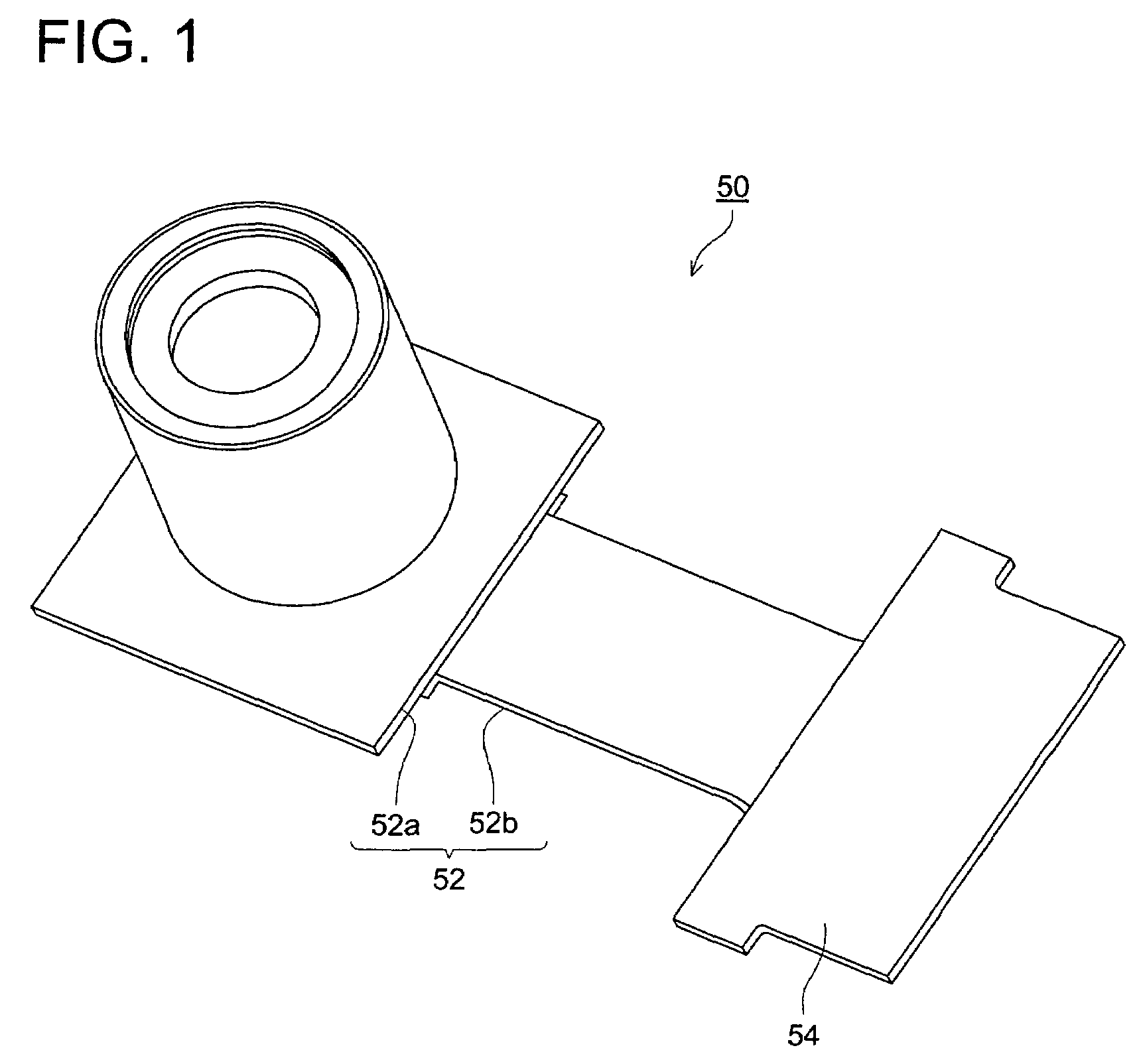
BACKGROUND OF THE INVENTION[0001]The present invention relates to an image pick-up lens which is preferable as an optical system of a solid-state imaging element such as a CCD type image sensor or a CMOS type image sensor, an image pick-up unit having the image pick-up lens, and a mobile terminal provided with this image pick-up unit.[0002]Recently, following the technical advantages-offering, and size reduction of an image pick-up device using the solid-state imaging element such as CCD (Charged Coupled Device)type image sensor or CMOS (Complementary Metal Oxide Semiconductor)type image sensor, a cell phone or a personal computer, provided with the image pick-up device, is spreading.[0003]Then, following an increase of the high density by the size reduction of these cell phone or personal computer, or an increase of functions, a request for more size reduction of the image pick-up lens mounted on the image pick-up device is emphasized to intend the size reduction of these image pic...

Claims


Application Information

Patent Timeline
Patent Type & Authority Patents(United States)
IPC IPC(8): G02B13/16G02B9/12G02B13/00H04N5/232G02B13/18H04N5/225
CPCG02B9/12G02B13/0035H04N5/2254G02B13/18H04N5/2253G02B13/16
Inventor YAMAGUCHI, SUSUMUSANO, EIGO
Owner KONICA MINOLTA OPTO
Learn More