
Methods and devices for tissue repair

Inactive Publication Date: 2005-02-10
SMITH & NEPHEW INC
View PDF98 Cites 469 Cited by
  • Summary
  • Abstract
  • Description
  • Claims
  • Application Information

AI Technical Summary

Benefits of technology

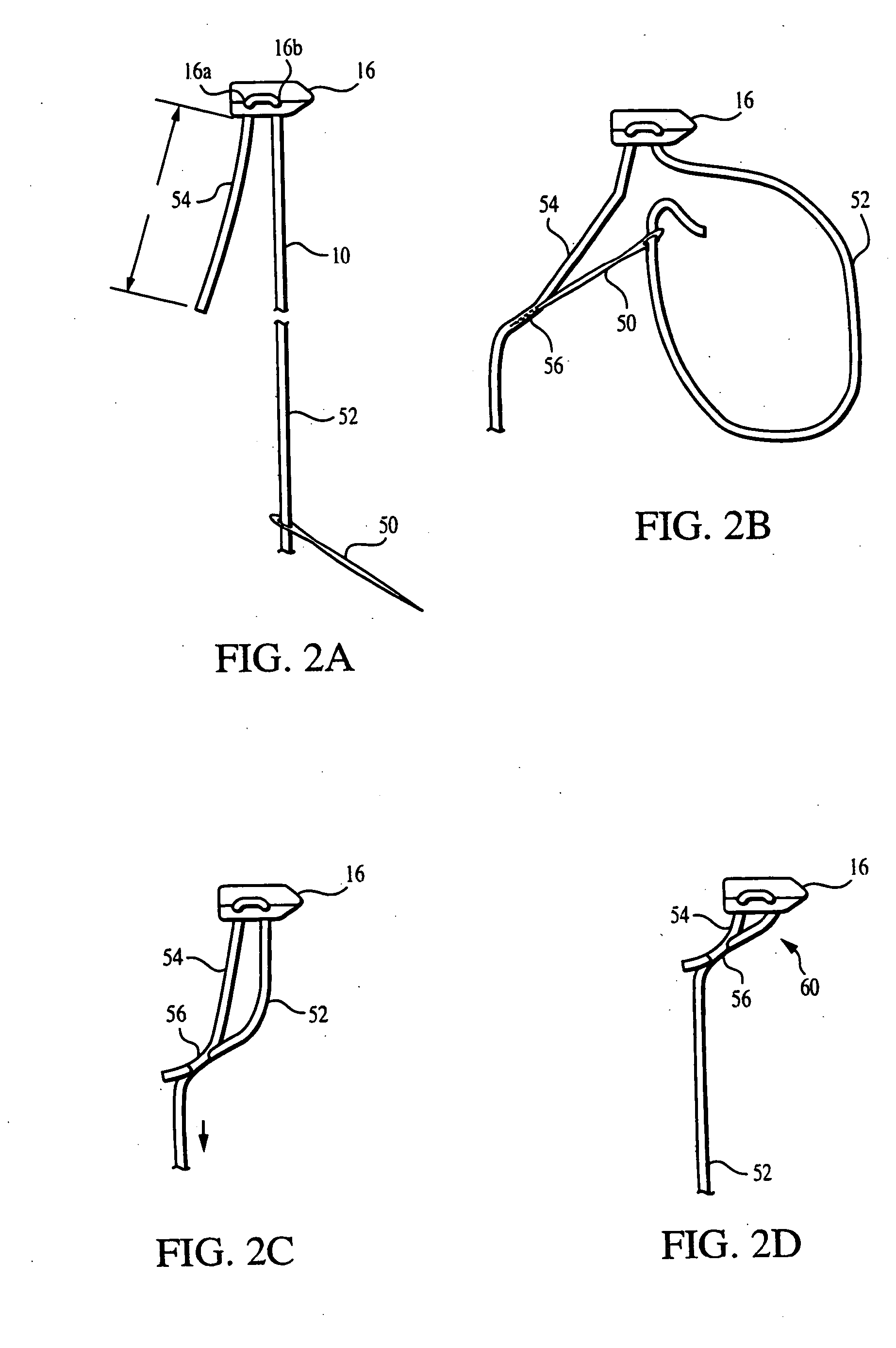
[0021] In another general aspect, a surgical assembly includes a first fastener, a second fastener, and a flexible member connecting the first fastener to the second fastener. The flexible member is movably attached to the second fastener, such that pulling on a free end of the flexible member shortens a length of the flexible member between the first and second fasteners.
[0098] Moreover, the procedure is simple and easy. For example, in one embodiment, the fastener is rotatably positioned within the bone, the delivery device is withdrawn, a knot pusher is used to tighten the slip knot to place the retainer against the tendon, and the proximal end of the suture is cut. Thus, the physician does not need to tie any knots or reach through tissue to manipulate any of the components used in the procedure.

Problems solved by technology

Thus, areas of poor blood supply in the rotator cuff make these tendons difficult and slow to heal following an injury, such as a tear to the supraspinatus muscle or the subscapularis muscle.

Method used


Image

  • Methods and devices for tissue repair
  • Methods and devices for tissue repair
  • Methods and devices for tissue repair

Examples


Embodiment Construction

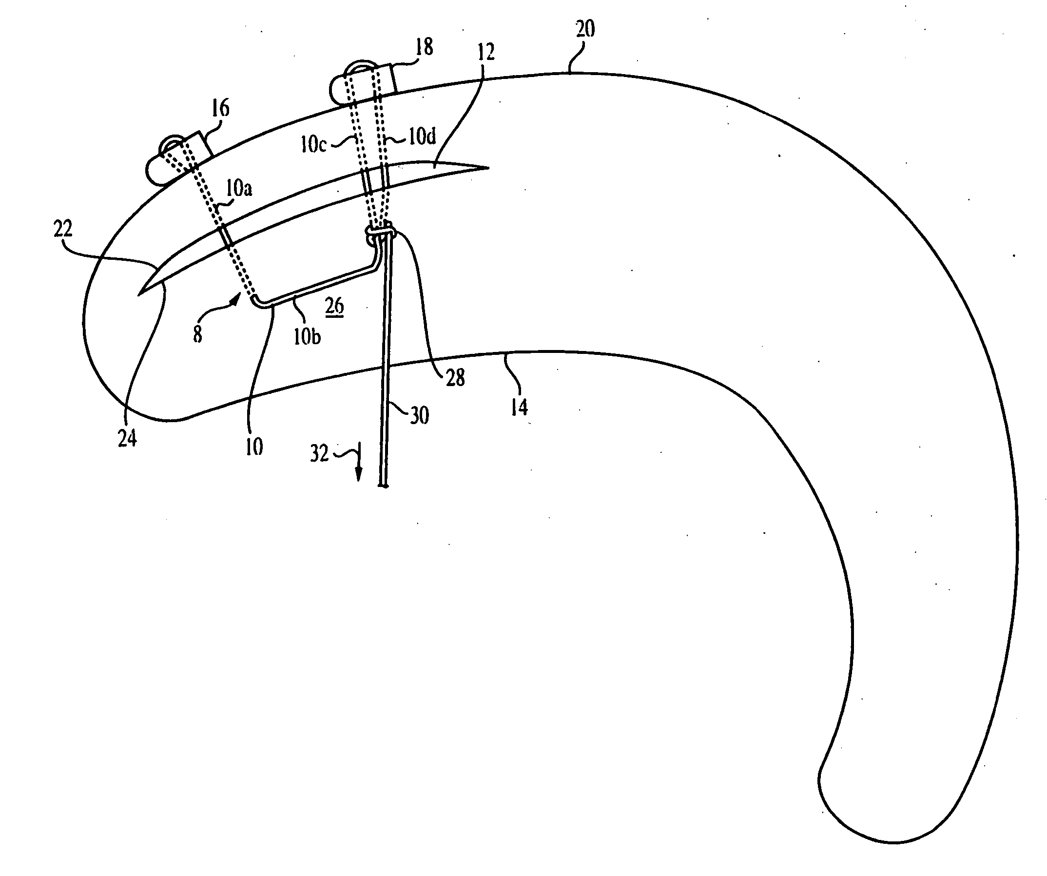
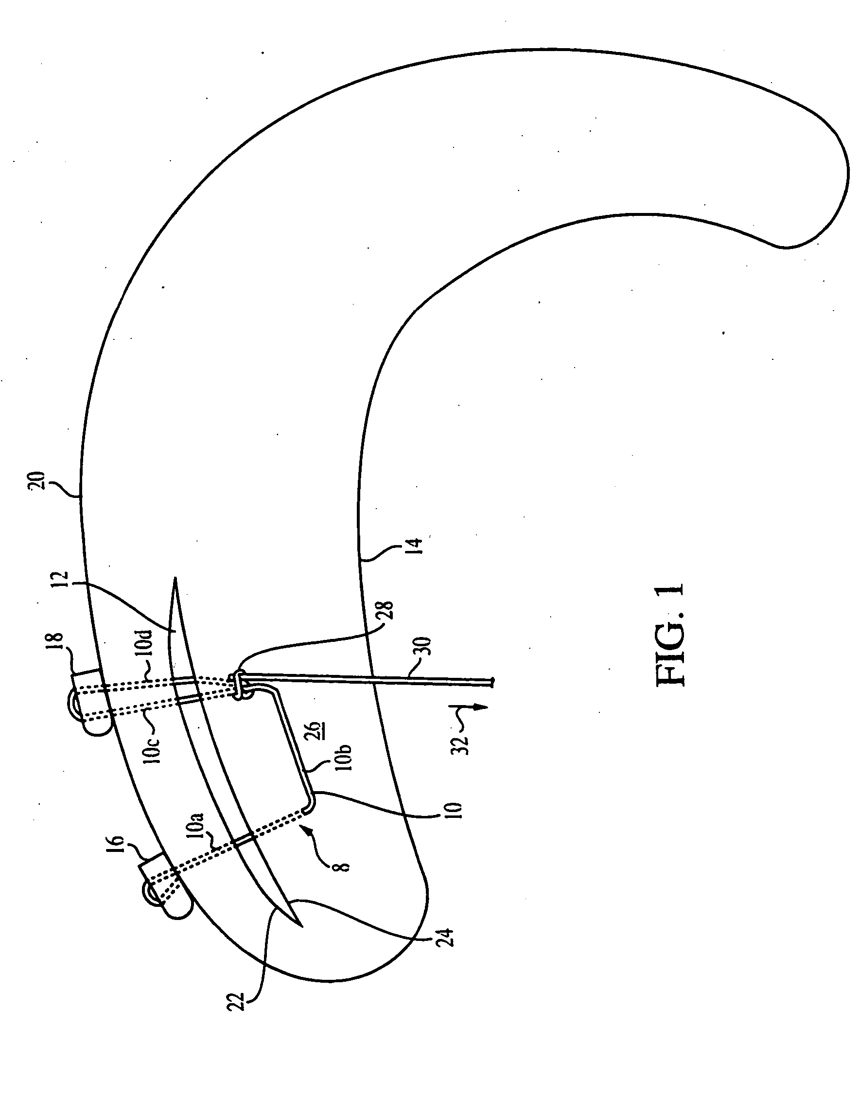
[0200] Referring to FIG. 1, a closure device 8 for mending a tear 12 in soft tissue 14, for example, the meniscus of the knee joint, includes a flexible member, for example, suture 10, coupled to a first fixation member (for example, a first retainer) 16 and a second fixation member (for example, a second retainer) 18. The meniscus is a C-shaped, rubbery, shock-absorbing structure located between the tibia and the femur inside the knee. Suture 10 is fastened to fixation member 16 to limit movement of suture 10 relative to the first fixation member 16, while suture 10 is movable relative to the second fixation member 18.

[0201] When implanted in the knee joint, the fixation members 16 and 18 lie on a surface 20 of tissue 14, for example, the outer surface of the meniscus. Suture 10 has a first suture length 10a extending from first fixation member 16 through tissue 14, traversing the tear 12, and emerging at a surface 26 of tissue 14; a second suture length 10b extending across the s...


PUM


Abstract

An apparatus includes first and second fixation members, a flexible member coupled to the first and second fixation members, and a limiting element coupled to the flexible member. The limiting element is movable relative to the second fixation member and acts to limit loosening of the flexible member relative to the second fixation member. The limiting element can be slidably received by the flexible member. The flexible member can be coupled to the fixation members such that pulling on a free end of the flexible member shortens a length of the flexible member between the fixation members.

Description

CROSS REFERENCE TO RELATED APPLICATIONS [0001] This application is a continuation of co-pending U.S. application Ser. No. 10 / 278,474, filed Oct. 23, 2002; which is a continuation-in-part of U.S. application Ser. No. 09 / 886,367, filed Jun. 22, 2001; which is a continuation of U.S. application Ser. No. 09 / 704,926, filed Nov. 2, 2000, and a continuation-in-part of U.S. application Ser. No. 09 / 453,120, filed Dec. 2, 1999, now abandoned. All of the above applications are incorporated herein by reference.TECHNICAL FIELD [0002] This application relates to devices and methods for repairing tissue. BACKGROUND [0003] One area in the body where soft tissue is surgically reattached to bone is the attachment of a rotator cuff tendon to the humerus. The rotator cuff tendons have areas of low blood supply. With an increased blood supply, a tissue, such as a tendon, can repair and maintain itself better and faster. Thus, areas of poor blood supply in the rotator cuff make these tendons difficult an...

Claims


Application Information

Patent Timeline
IPC IPC(8): A61B17/04A61B17/06A61B17/064A61F2/08
CPCA61B17/0401A61B17/06066A61B17/0469A61B17/0487A61B17/06109A61B17/06166A61B2017/0404A61B2017/0409A61B2017/0412A61B2017/0414A61B2017/0417A61B2017/0427A61B2017/0437A61B2017/044A61B2017/0445A61B2017/0458A61B2017/0464A61B2017/0475A61B2017/0477A61B2017/0496A61B2017/061A61B2017/0646A61B2017/0647A61B2017/0648A61F2/0805A61F2/0811A61F2002/0829A61F2002/0852A61F2002/0858A61F2002/0882A61F2002/0888A61B17/0467
Inventor BOJARSKI, RAYSIKORA, GEORGETORRIE, PAUL ALEXANDEREK, STEVEN
Owner SMITH & NEPHEW INC
Learn More