
Riveting system

a technology of riveting system and riveting plate, which is applied in the direction of mechanical measuring arrangement, shape safety device, instruments, etc., can solve the problems of high cost of producing such joining devices, inability to achieve high-quality punch rivet connections, and inability to ensure the quality of punch rivet connections, etc., to achieve less fluid spillage mess, improve accuracy, and reduce maintenance

Inactive Publication Date: 2009-07-14
NEWFREY
View PDF21 Cites 29 Cited by
  • Summary
  • Abstract
  • Description
  • Claims
  • Application Information

AI Technical Summary

Benefits of technology

The present invention is a riveting system that uses a self-piercing rivet and an electronic control unit to determine riveting characteristics and actuator characteristics. The system employs an electric motor to drive a nut and spindle drive transmission which converts rotary actuator motion to linear rivet setting motion. The system is compact, mechanically efficient, and provides higher accuracy, repeatability, and quality control compared to traditional hydraulic drive machines. The system also uses multiple rivet feeders to select different types of rivets and ensures real-time quality control and monitoring of the rivet, riveted joint, workpiece characteristics, actuator power consumption, and actuator power output characteristics. The system provides a high-quality and repeatable riveted joint that is flush with the punch-side workpiece outer surface without fully piercing through the die-side workpiece. The system can easily vary or alter the performance characteristics by training the set points using training techniques without requiring mechanical alterations in the machinery.

Problems solved by technology

A plunger punches the rivet through the workpieces such that the rivet punches a hole in the parts thereby rendering pre-punching unnecessary.
The cost of producing such joining devices is relatively high and process controls for achieving high quality punch rivet connections has been found to be problematic.
In particular, hydraulically operated joining devices are subject to variations in the force exerted by the plunger owing to changes in viscosity.
A further drawback of hydraulically operated joining devices is that the hydraulic medium, often oil, has a hydroscopic effect thereby requiring exchange of the hydraulic fluid at predetermined time intervals.
Moreover, many hydraulic systems are prone to hydraulic fluid leakage thereby creating a messy work environment in the manufacturing plant.

Method used


Image

  • Riveting system
  • Riveting system
  • Riveting system

Examples


Embodiment Construction

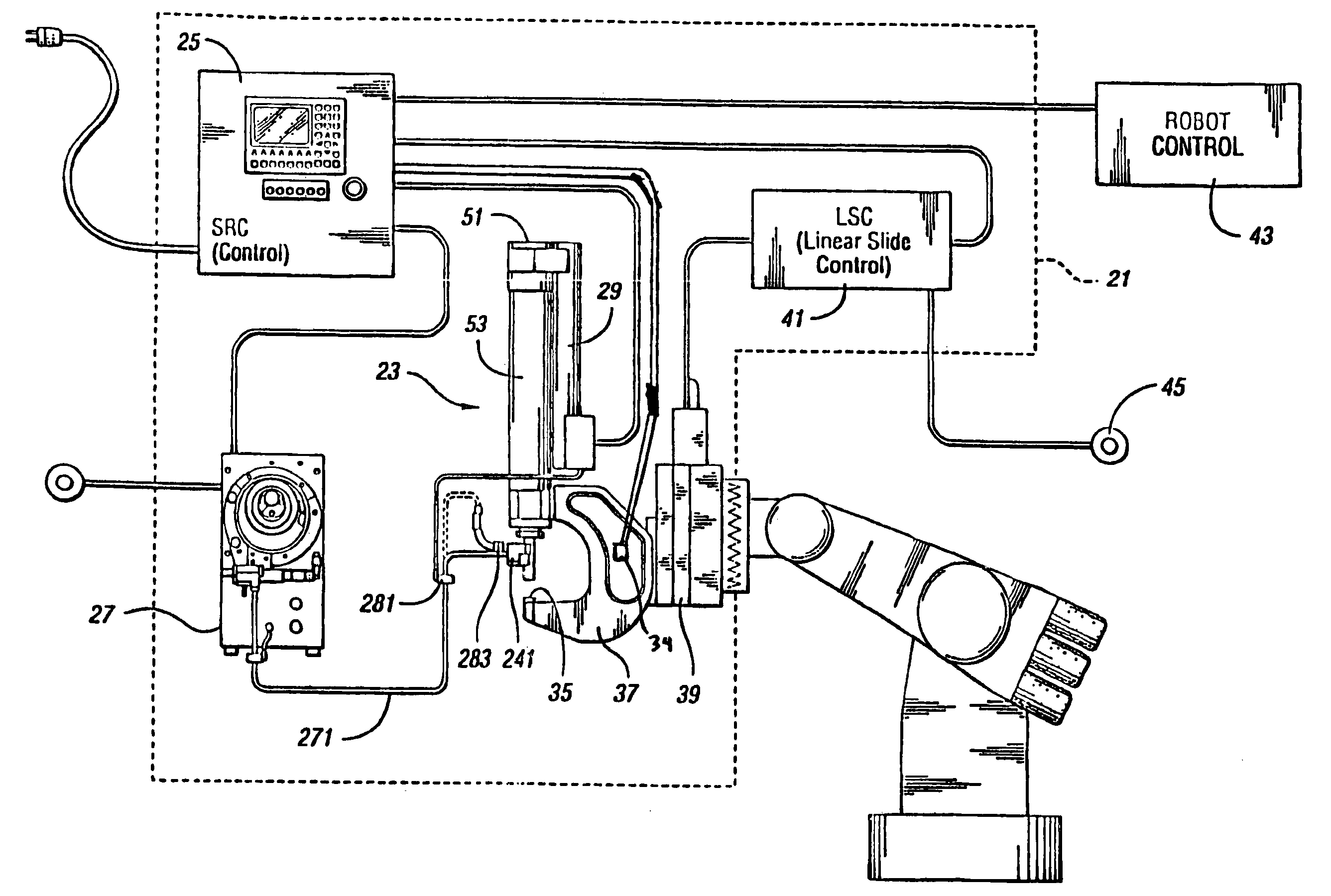
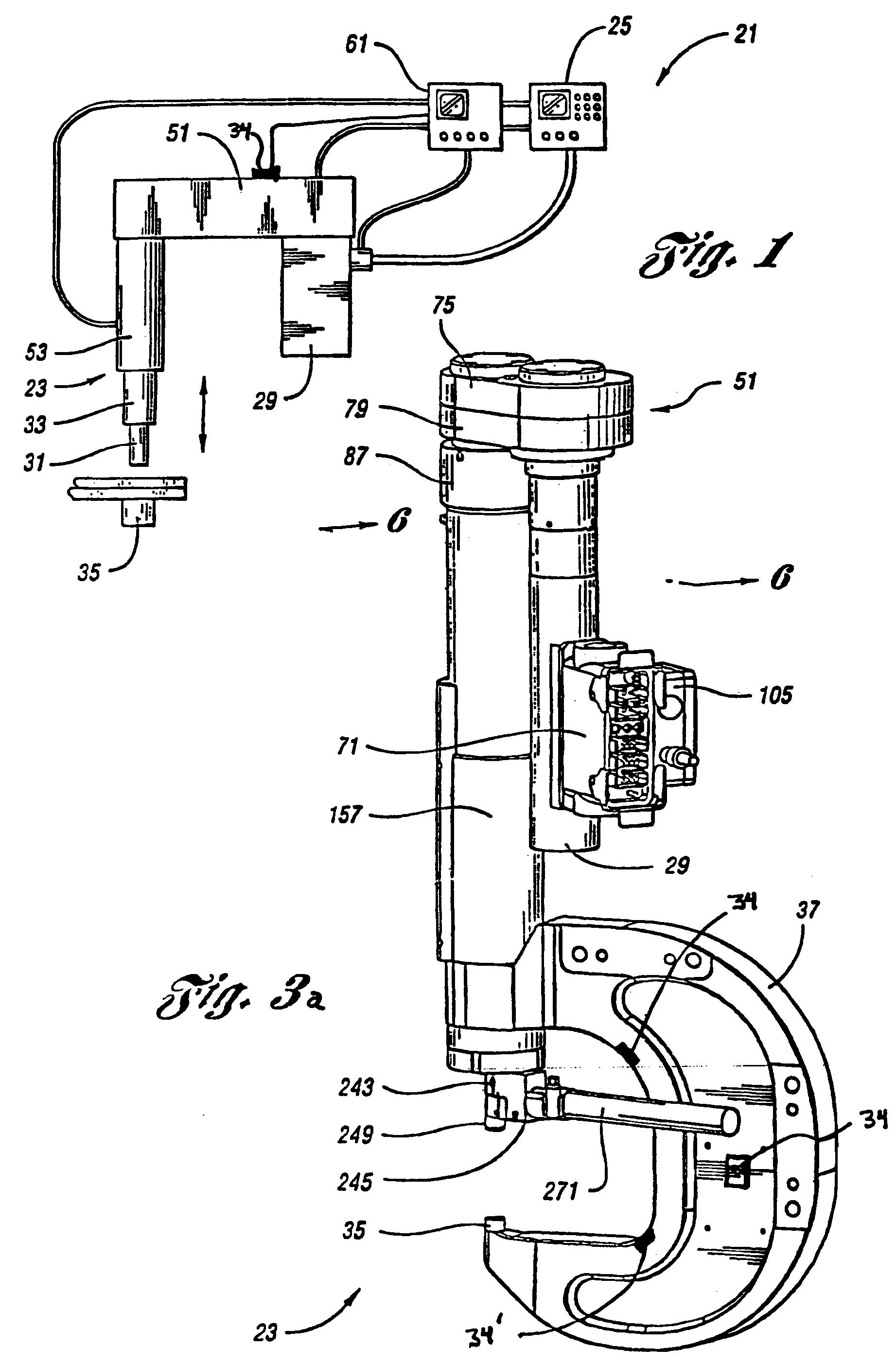
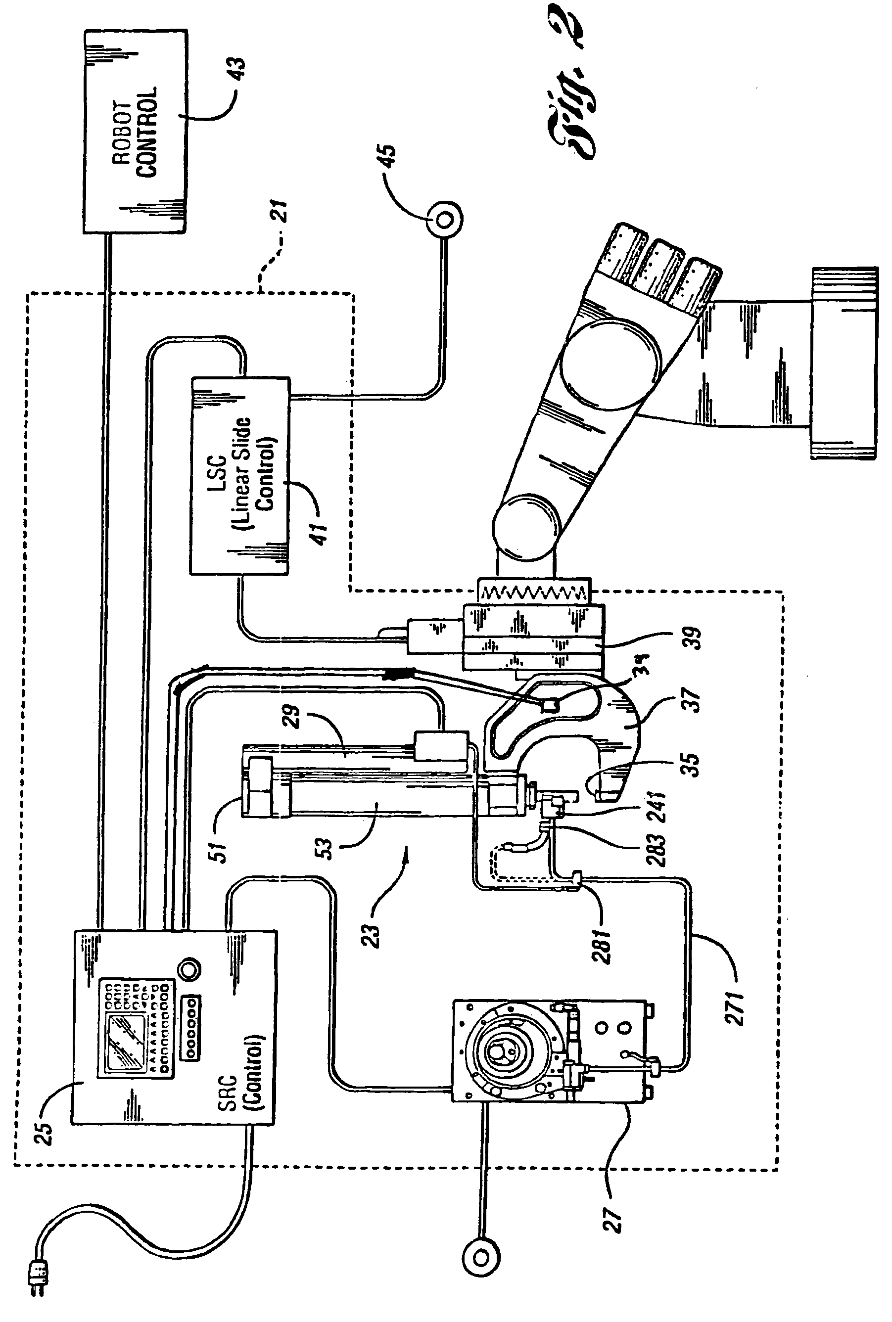
[0039]The following description of the preferred embodiments is merely exemplary in nature and is in no way intended to limit the invention, its application, or uses. Generally speaking, the system sets a fastener for joining parts. The system is configured to confirm the quality of the setting process and of the resultant set. The system uses a rivet setting machine having a first member configured to apply a setting force to a fastener to set the fastener. A coupling structure is provided which is configured to apply reaction forces to the first member in response to the setting force. A sensor is attached to the coupling structure for sensing changes in physical parameters within said coupling structure induced by the reaction forces.

[0040]The first member applies the setting force along an axis to a first side of the fastener and the setting force is resisted by a second member which applies a reaction force generally parallel to setting force. This reaction force is caused by e...


PUM

PropertyMeasurementUnit
biasing forceaaaaaaaaaa
cycle timeaaaaaaaaaa
thicknessaaaaaaaaaa

Abstract

A riveting system is operable to join two or more workplaces with a rivet. In another aspect of the present invention, a self-piercing rivet is employed. Still another aspect of the present invention employs an electronic control unit and one or more sensors to determine a riveting characteristic and / or an actuator characteristic.

Description

CROSS-REFERENCE TO RELATED APPLICATIONS[0001]This application is a continuation of PCT International Application No. PCT / US2005 / 009505, filed Mar. 22, 2005, which claims the benefit of U.S. Provisional Applications Ser. No. 60 / 555,989 filed Mar. 24, 2004, Ser. No. 60 / 567,576 filed May 3, 2004, Ser. No. 60 / 587,971 filed Jul. 14, 2004, Ser. No. 60 / 589,149 filed Jul. 19, 2004, Ser. No. 60 / 612,772 filed Sep. 24, 2004, and Ser. No. 60 / 625,715 filed Nov. 5, 2004. The disclosures of the above applications are incorporated herein by reference.FIELD OF THE INVENTION[0002]This invention relates generally to riveting and more particularly to a riveting system and a process for forming a riveted joint.BACKGROUND OF THE INVENTION[0003]It is well known to join two or more sheets of metal with a rivet. It is also known to use self-piercing rivets that do not require a pre-punched hole. Such self-piercing or punch rivet connections can be made using a solid rivet or a hollow rivet.[0004]A punch riv...

Claims


Application Information

Patent Timeline
Patent Type & Authority Patents(United States)
IPC IPC(8): B23P21/00B21J15/02B21J15/06B21J15/10B21J15/28
CPCB21J15/025B21J15/105B21J15/26B21J15/28B21J15/285B21J15/10Y10T29/5377Y10T29/53422Y10T29/5343Y10T29/49764Y10T29/53039Y10T29/53013Y10T29/5307Y10T29/53009Y10T29/53496Y10T29/49771
Inventor CHITTY, EYMARD JTAYLOR, BRIAN MTHOMAS, PETER CVIGLIOTTI, DANIEL P
Owner NEWFREY
Learn More