
Thermite charge

a technology of thermal energy and charge, applied in the field of thermal energy charge, can solve the problems of time-consuming, dangerous, expensive, etc., and achieve the effect of improving safety

Active Publication Date: 2009-07-07
BATTELLE MEMORIAL INST
View PDF9 Cites 19 Cited by
  • Summary
  • Abstract
  • Description
  • Claims
  • Application Information

AI Technical Summary

Benefits of technology

Enables efficient, safe, and precise linear or curvilinear cuts in materials with reduced preparation needs, effectively handling discontinuities and varying thicknesses, and achieving penetration times comparable to explosive shape charges with enhanced safety and logistical advantages.

Problems solved by technology

This process is time consuming, expensive, and dangerous.

Method used


Image

  • Thermite charge
  • Thermite charge
  • Thermite charge

Examples


Embodiment Construction

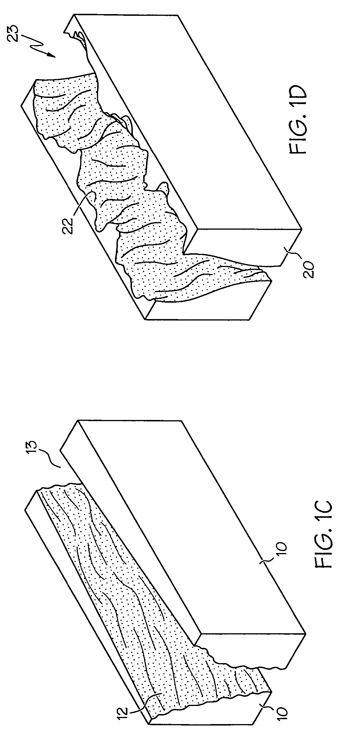
[0027]Broadly, the invention includes apparatus and methods of cutting materials using a linear, or curvilinear nozzle where the nozzle may be a long linear nozzle (see FIG. 10), an array of a series of elongated nozzles that may be rectangular or square (see FIG. 11), or an array of a series of circular nozzles (see FIG. 12). Hot reaction products (typically hot thermite reaction products) are ejected from the nozzle under pressure and erode, spall, oxidize or reduce a target material or materials. In some cases the hot reactants react with the target material or materials. The invention typically allows the cutting of very resistant materials including concrete and contained rebar (reinforced concrete) in a single step using a non-explosive, hot jetting material.

[0028]The materials used for the thermite reaction may be premixed or mixed immediately prior to being jetted into the target material. One method for mixing the materials is to fluidize one solid reactant (typically powde...


PUM

PropertyMeasurementUnit
temperaturesaaaaaaaaaa
temperatureaaaaaaaaaa

Abstract

The present invention provides for cutting operations using linear thermite charges; the charges cut one dimensional or two dimensional geometric shapes; the invention is useful for structure entry or demolition.

Description

[0001]This application claims the benefits of U.S. Provisional Application No. 60 / 659,677 filed Mar. 8, 2005.[0002]The entire contents of the provisional application are incorporated herein by reference.FIELD OF THE INVENTION[0003]The invention relates to thermite charges that are useful for cutting materials including metals, masonry, reinforced concrete, rock, and the like. The invention allows more expeditious and safer material removal, including entry into structures, and structural demolition.BACKGROUND OF THE INVENTION[0004]Thermite reactions are well characterized and have been used for a variety of applications, including demilitarization of expended ordnance, quick repair welding of railroad tracks, and cutting applications using lances or burning bars. The thermite reaction is an exothermic reaction that can produce temperatures of more than 4,000° F. These temperatures are well above the melting point of most metals. Boosting the rate of the thermite reaction by flowing ...

Claims


Application Information

Patent Timeline
Patent Type & Authority Patents(United States)
IPC IPC(8): F42D3/00B23K7/00
CPCC06B33/00C06B45/00F42D3/02F42D3/00F42B1/02
Inventor GIVENS, RICHARD W.KLEIN, JEROME A.BURKY, THOMAS E.REUTHER, JAMES J.
Owner BATTELLE MEMORIAL INST
Learn More