
Adjusting data burst transmission rates

a data burst and transmission rate technology, applied in the field of data transmission, can solve the problems of large power consumption of the terminal, disruption of selective reception of content or services, and long operation time of the terminal, so as to reduce the length of time that the receiver is in the receiver's place, reduce power consumption, and increase the available transmission rate

Inactive Publication Date: 2009-06-23
WSOU INVESTMENTS LLC
View PDF7 Cites 2 Cited by
  • Summary
  • Abstract
  • Description
  • Claims
  • Application Information

AI Technical Summary

Benefits of technology

"The patent describes a method and apparatus for broadcasting data in a cellular communication system with two cells. The method involves synchronizing the start times of bursts of data in the two cells so that the time intervals between bursts in each cell are the same. This allows a terminal to continue selective reception of the bursts with little or no disruption. The method also allows for the addition of additional data to the bursts, which can be based on the transmission rates of the cells. The additional data can be interleaved with the data in the bursts or added to the end of each burst. The technical effect of this invention is to improve the reliability and stability of data transmission in a cellular communication system."

Problems solved by technology

Such a terminal may be required to operate for lengthy periods of time using only an internal source of power.
In the case of simplex broadcast systems supporting unidirectional data delivery, e.g. DVB-T or DVB-S networks, a large proportion of the power consumption of the terminal arises from the demands of a receiver when receiving data.
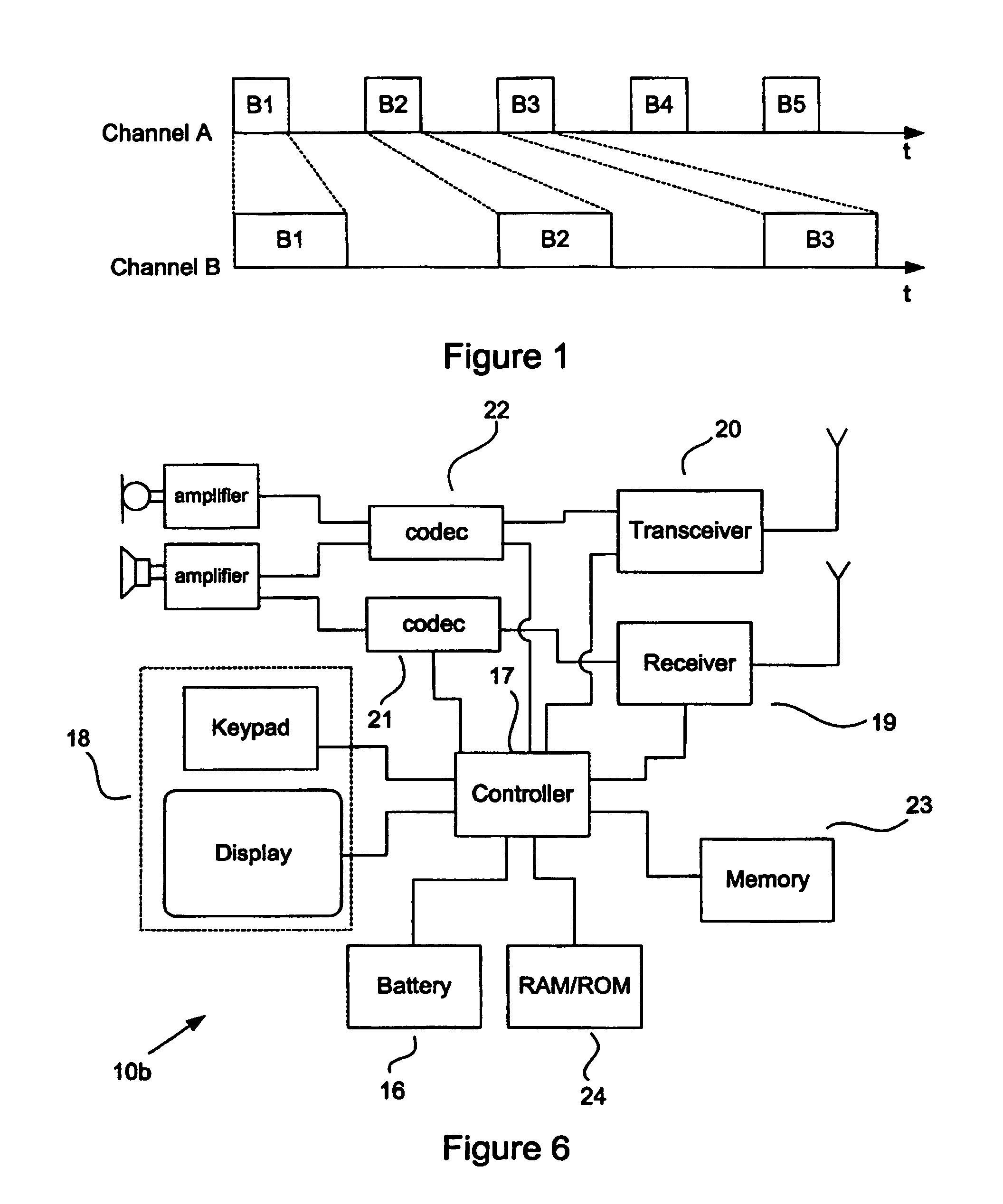
Problems may arise when a terminal moves from a location covered by a first cell, within which channel A is received, to another covered by a second cell, where the terminal receives the same data over channel B, as the increasing time offset between transmission of the corresponding bursts over channels A, B will disrupt selective reception of content or services in that terminal.

Method used


Image

  • Adjusting data burst transmission rates
  • Adjusting data burst transmission rates
  • Adjusting data burst transmission rates

Examples


first embodiment

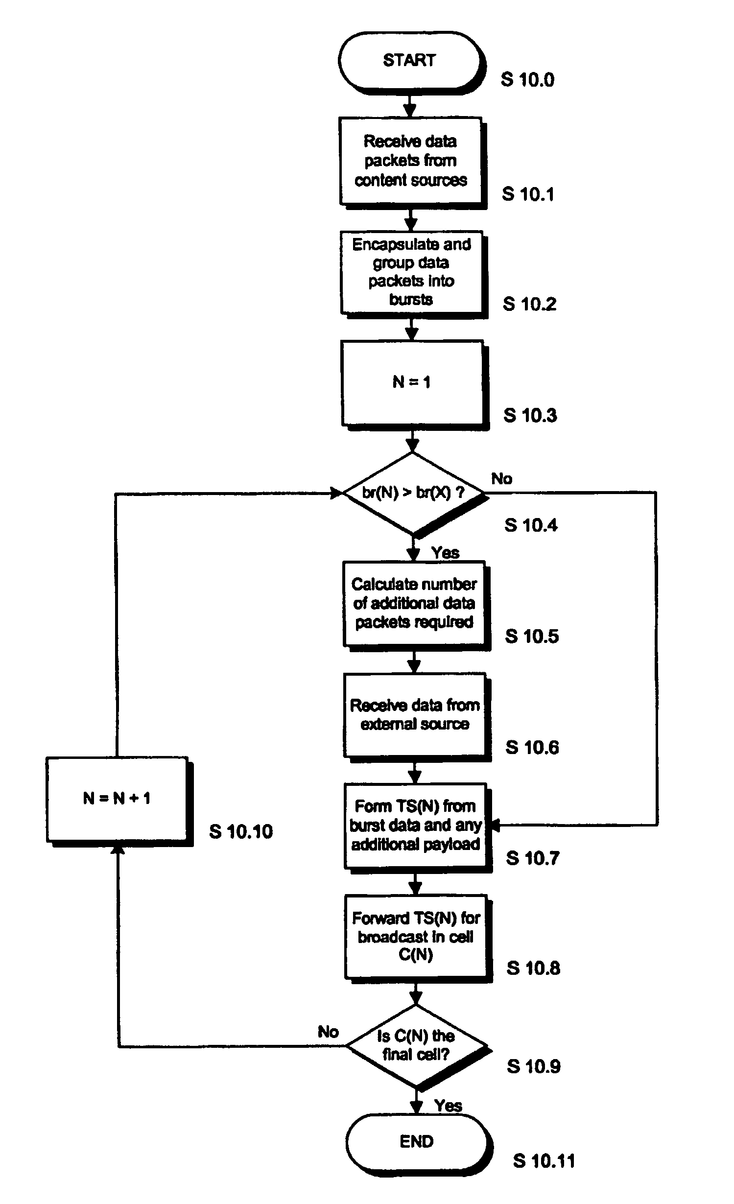
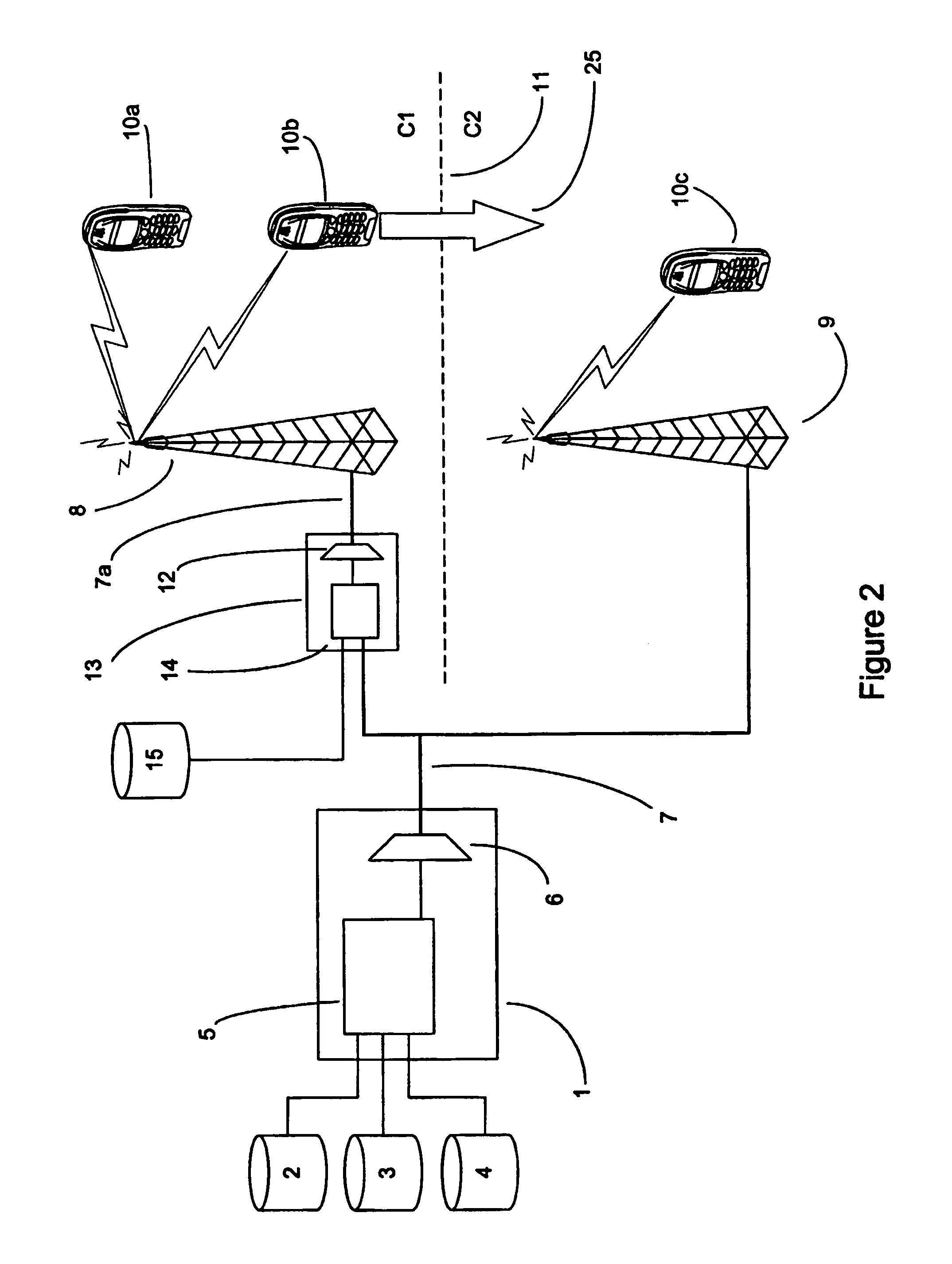
[0032]FIG. 2 shows a communication system according to the invention, in which a broadband digital broadcast head-end 1 is connected to a variety of content sources 2, 3, 4. Data packets relating to services and / or content, e.g. audio-visual content, data files, images, are delivered to the head-end 1. In this example, the data packets are in the form of IPv4 or IPv6 datagrams, although the invention is not limited to IP data delivery.

[0033]The data packets are encapsulated by a data processor 5 at the head-end 1 and grouped together into one or more bursts, which have a bandwidth equal to or approaching the maximum available bandwidth. A set of data packets relating to a particular service or the same content are arranged in the same burst or series of bursts, although a single burst may contain a plurality of sets of data packets that are unrelated to each other to ensure efficient use of bandwidth. The bursts are multiplexed by a multiplexer 6 according to a TDMA scheme. In this ...

second embodiment

[0041]The burst rate adjustment process of FIG. 3 synchronises the data bursts so that a time interval ti between adjacent bursts B1-B5 in the series is the same in both cells C1, C2. The data bursts may be synchronised so that the transmission of each burst B1-B5 in the series begins in cells C1, C2 simultaneously, as shown in FIG. 4. Alternatively, according to the invention, the start times may be synchronised so that there is a fixed time offset to between a start time in cell C1 and a start time in cell C2 for each burst B1-B5 in the series, as shown in FIG. 5.

[0042]The synchronisation of the data bursts between cells C1, C2 minimises disruption of data reception when a terminal 10b moves from a location covered by the first cell C1 to another covered by the second cell C2 or vice versa. An example of a suitable terminal, here a mobile telecommunications device 10b, is shown in detail in FIG. 6 and comprises an internal power supply, preferably in the form of a rechargeable bat...

third embodiment

[0046]FIG. 7 depicts the broadcast of series of bursts B1-B5 according to the invention. In this embodiment, the payload P2 is calculated as described above however, instead of adding the additional data L1-L5 in a burst at the end of each burst B1-B5, the additional data packets are interleaved with the data packets in each burst B1-B5, so that both the start and end times of bursts in cells C1, C2 are synchronised. Therefore, where a terminal 10b moves from cell C2 to cell C1, the calculation of the expected burst start time by the controller 17 may continue with little or no disruption, as the burst interval ti and, in this particular example, the burst start times and burst lengths, are unchanged.


PUM


Abstract

A broadcast service for transmission to mobile terminals 10a-10c in a cellular communication system comprises a series of burst B1-B5 of data packets in a transport stream 7. Where the available data transmission rates in cells C1, C2 are unequal, the transport stream 7a for transmission to the cell C1 with the higher data transmission rate is modified by incorporating additional payload L1-L5 in each burst in the series, for example by appending the additional payload to each burst or by interleaving the burst data and additional payload (FIG. 7) so that a time interval t; between adjacent bursts B1-B5 is the same in both cells C1, C2. Therefore, start times of the transmission of each burst B1-B5 in both cells C1, C2 are synchronised, i.e. the transmission of each burst B1-B5 begins simultaneously in both cells C1 or a time interval to between the start of transmission of each burst in cells C1, C2 is fixed (FIG. 5). This allows a mobile terminal 10b operating in a selective data reception mode to continue receiving a service without disruption when moving across a cell boundary 11. The incorporation of the additional payload may be performed by a digital broadcast head-end 26 or by an apparatus 13 associated with a transmitter 8 serving a cell C1.

Description

FIELD OF THE INVENTION[0001]The invention relates to the transmission of data in a broadcast data service. The invention is particularly suitable for, but not limited to, broadcasting data to mobile terminals.BACKGROUND OF THE INVENTION[0002]The provision of a broadcast service may require the transmission of one or more to of video, audio and other data signals. For example, a service may include a first stream carrying primary content, such as live or recorded music or a multimedia clip, and further streams carrying secondary content, such as error correction data, subtitles or song lyrics. Such services can be broadcast in a multiplexed transport stream using digital broadcasting networks, e.g. terrestrial Digital Video Broadcast (DVB-T), Integrated Services Digital Broadcasting (ISDB-T) or Advanced Television Systems Committee (ATSC-T), DVB-S (satellite), DVB-C (cable) or digital audio broadcasting (DAB) systems.[0003]Wireless communication systems typically include one or more ...

Claims


Application Information

Patent Timeline
Patent Type & Authority Patents(United States)
IPC IPC(8): H04K1/02H04B7/005H04B7/26H04H20/33H04W16/06
CPCH04H20/18H04W16/06H04H20/33
Inventor PAILA, TONIPEKONEN, HARRI
Owner WSOU INVESTMENTS LLC
Learn More