
Communication system and method for controlling the same

a communication system and communication technology, applied in the field of communication systems, to achieve the effect of efficient process, efficient process, and efficient operation

Inactive Publication Date: 2007-01-11
NEC CORP
View PDF8 Cites 38 Cited by
  • Summary
  • Abstract
  • Description
  • Claims
  • Application Information

AI Technical Summary

Benefits of technology

[0022] An object of the present invention is to solve such conventional problems and to provide an efficient and stable communication system and a system control method that enables efficient and stable operation.
[0027] As an embodiment of the present invention, when the measured value of the monitored item exceeds a first fault-detection threshold, frame synchronization is performed as the recovery, wherein the frame synchronization is performed by: generating an error rate by comparing a part of the first data stored in the first communication device with a part of the second data stored in the second communication device while changing a bit-to-bit correspondence between the first data and the second data; and searching for a bit-to-bit correspondence which minimizes the error rate or provides an error rate lower than the first fault-detection threshold.
[0034] The third controller may perform timing correction as the recovery when the measured value of the monitored item is equal to or lower than the second fault-detection threshold and exceeds a third fault-detection threshold, wherein the timing correction is performed by: generating the error rate while changing the operation timing in at least one of the first controller and the second controller; and searching for an operation timing which minimizes the error rate.
[0035] According to the present invention, at least one monitored item and its fault-detection threshold value are preset. A fault is identified based on a measurement value for the monitored item and its fault-detection threshold value, and individual recovery is performed depending on the identified fault. Accordingly, recovery processing appropriate to the fault factor can be performed. It is possible to efficiently avoid stopping the process of key generation as a result of treating all fault factors alike as in the cases of conventional technologies. This makes it possible that the process of key generation is continued by performing recovery processing appropriate to a fault for which the key generation process does not need to be stopped. Accordingly, as a whole, the efficient process can be performed.
[0036] Moreover, a fault factor is identified with the consideration of not only a processing timing deviation between the sender and receiver but also a processing timing deviation occurring inside the receiver, whereby appropriate recovery processing can be performed. Accordingly, it is possible to achieve a stable and highly reliable communication system.
[0037] In the case of applying the present invention to a quantum key distribution system in particular, a cryptographic key can be stably generated. According to conventional quantum key distribution technologies, degradation in the error rate (QBER) means the presence of an eavesdropper. However, according to the present invention, before the generation of a cryptographic key is stopped, various types of recovery processing can be performed depending on the contents of a fault, which can eliminate the cases where deterioration in the error rate due to an environmental change, a communication error or the like is misidentified as the presence of an act of eavesdropping. Consequently, even if a fault occurs, which should have caused the key generation to be stopped in a conventional case, the cryptographic key generation can be resumed. Accordingly, it is possible to achieve stable operation for cryptographic key generation over a long time. Moreover, with a plurality of monitored items and their fault-detection threshold values, fault factors can be handled separately, and individual recovery processing can be performed depending on each fault factor. As a result, it is possible to reduce the length of time required for recovery processing and to increase accordingly the time proportion that can be allotted for the cryptographic key generation.

Problems solved by technology

The monitored item may be an error rate, a change rate of the error rate, a shared data generation rate, or the like.

Method used


Image

  • Communication system and method for controlling the same
  • Communication system and method for controlling the same
  • Communication system and method for controlling the same

Examples


first embodiment

3. First Embodiment

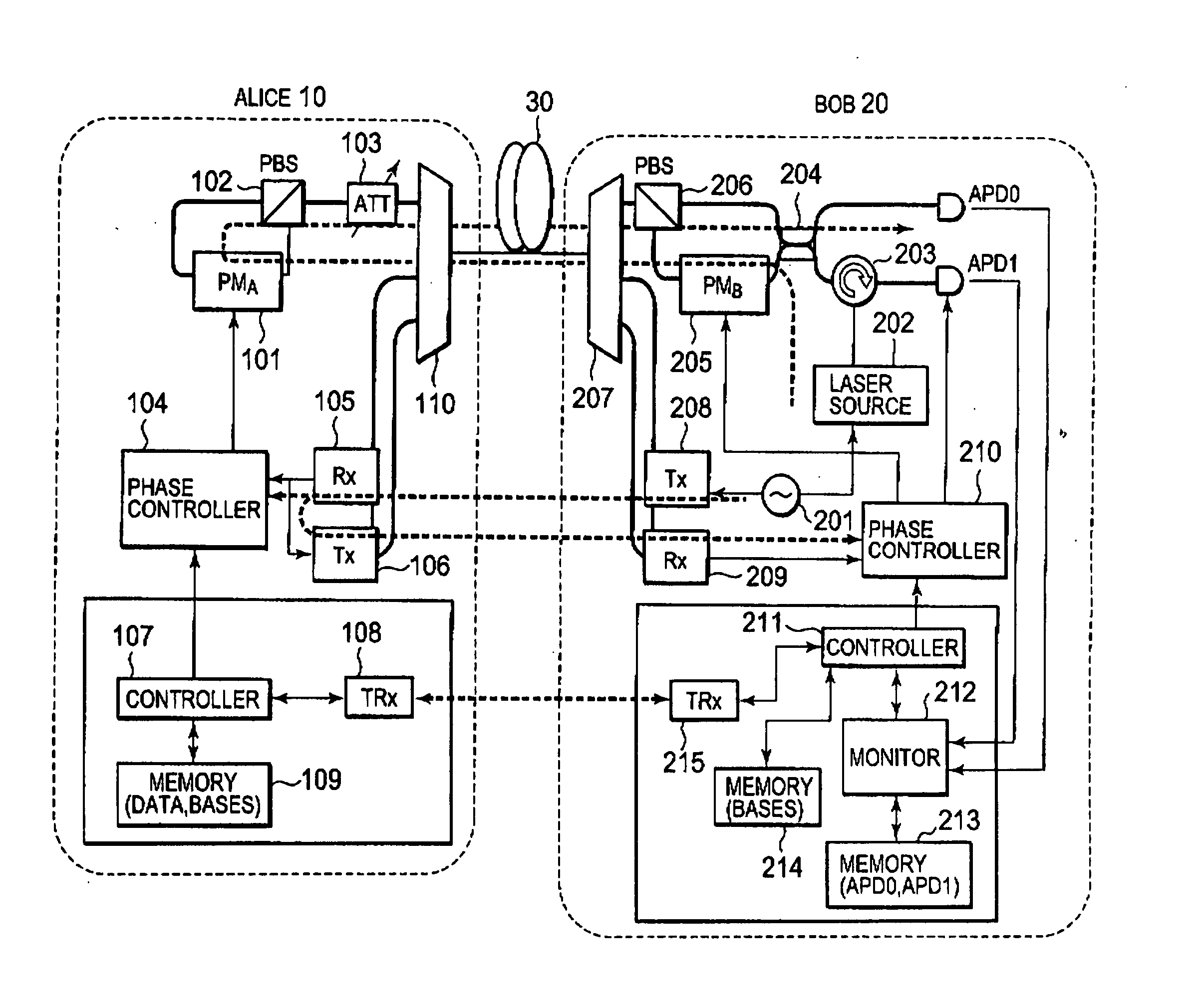
[0081] First, in a first embodiment, the following four points are assumed as factors for system faults in a quantum key distribution system. [0082] (1) Frame synchronization deviation: deviation in frame synchronization between Alice and Bob or deviation in frame synchronization inside Bob. [0083] (2) Modulation / detection phase deviation: deviation of a clock phase for photon-pulse modulation and / or deviation of a clock phase for photon-pulse detection. [0084] (3) Presence of an eavesdropper (Eve): deterioration in the rate of cryptographic key generation due to an act of eavesdropping. [0085] (4) Light source / photo detector fault: fault of a device for generating photon pulses and / or fault of a device for detecting photon pulses.

[0086] Although the details of these faults will be described later, it can be seen that different types of faults cause different levels of deterioration in the error rate QBER. Therefore, in the present embodiment, a threshold value Q...

second embodiment

4. Second Embodiment

[0156] In the above-described first embodiment of the present invention, the detection of a system fault is performed by monitoring QBER. According to a second embodiment of the present invention, the detection of a system fault is performed by also monitoring the rate of raw key generation in addition to QBER. Note that the configuration of a quantum key distribution system to which the second embodiment of the present invention is applied is basically similar to the system configuration shown in FIG. 4, except that the monitor 212 in the receiver 20 monitors the rate of raw key generation as well as QBER.

[0157] Although the monitoring of QBER by the monitor 212 is performed as in the first embodiment, the monitoring of the raw key generation rate VR is performed by using the number of photon counts per unit time. For example, in the system of FIG. 4, when photons are sequentially detected by the Geiger-mode-driven photo detector APD0 or APD1, corresponding bit...

third embodiment

5. Third Embodiment

[0182] In a third embodiment of the present invention, fault factors are separated by monitoring the amount of change in QBER. The configuration of a quantum key distribution system to which the third embodiment of the present invention is applied is basically similar to the system configuration shown in FIG. 4, except that the monitor 212 in the receiver 20 calculates the amount of change in QBER (hereinafter, referred to as QBER change rate).

[0183]FIG. 16 is a flowchart showing a method for controlling a communication network according to the third embodiment of the present invention. Note that steps similar to those in the first embodiment are denoted by the same reference symbols and numerals as those used in the first embodiment, and description thereof will be omitted.

[0184] Referring to FIG. 16, the monitor 212 monitors QBER as described above and calculates a difference from the past QBER stored in the memory 213, thereby calculating the QBER change rate...


PUM


Abstract

For an error rate QBER, threshold values are preset, including a threshold value Qbit for frame synchronization processing, a threshold value Qphase for phase correction processing, and a threshold value QEve for eavesdropping detection. Upon the distribution of a quantum key from a sender to a receiver, when the measurement value of QBER is deteriorated more than Qbit, frame synchronization processing is performed. When the measurement value of QBER is deteriorated more than Qphase, phase correction processing and frame synchronization processing are performed. When QBER does not become better than QEve even after these recovery-processing steps are repeated N times, it is determined that there is a possibility of eavesdropping, and the processing is stopped.

Description

BACKGROUND OF THE INVENTION [0001] 1. Field of the Invention [0002] The present invention relates to a system and method for monitoring degradation in the communication quality of a communication system and, when detecting it, recovering from the degradation. [0003] 2. Description of the Related Art [0004] The internet, which continues growing rapidly, is convenient on one hand, but its security is quite uncertain on the other hand. There is an increasing need for cryptographic technologies in order to maintain the secrecy of communications. Cryptographic schemes currently used in general can be classified into two categories: private key cryptography such as DES (Data Encryption Standard) and triple DES, and public key cryptography such as RSA (Rivest Shamir Adleman) and ECC (Elliptic Curve Cryptography). However, these techniques are cryptographic communication methods that ensure the security of communications based on the “complexity of computation” and are always fraught with t...

Claims


Application Information

Patent Timeline
Patent Type & Authority Applications(United States)
IPC IPC(8): H04L9/30H04B10/07H04L9/12H04B10/2507H04B10/556H04B10/70
CPCH04L1/242H04L9/0858H04L2209/34
Inventor TANAKA, AKIHIROTAJIMA, AKIOTAKAHASHI, SEIGOMAEDA, WAKAKO
Owner NEC CORP
Learn More