
Adaptive equalizing apparatus and method

a technology of equalizing apparatus and adapter, which is applied in the direction of digital signal error detection/correction, line-faulst/interference reduction, and with built-in power, etc., can solve the problems of reducing the bit error rate (ber), degrading the decoder performance to a large extent, and achieving a lower error rate

Inactive Publication Date: 2009-06-23
SONY CORP
View PDF29 Cites 15 Cited by
  • Summary
  • Abstract
  • Description
  • Claims
  • Application Information

AI Technical Summary

Benefits of technology

The patent text describes an adaptive equalizing apparatus and method that combines partial response equalization and maximum-likelihood decoding to improve the performance of decoding and remove distortion in a read signal. The apparatus and method can adapt to the asymmetry of the input waveform and remove leading edge interference. The technical effects of the invention include improved performance of decoding, reduced bit error rate, and improved detection of non-linear equalization errors.

Problems solved by technology

However, in case PR equalization is made of an input waveform including insufficient or no frequency components required for the PR equalization, there will occur a frequency domain which cannot be equalized by any means.
Such an error will remain as an equalization error greatly depending upon a pattern of input data, degrade the decoder performance to a large extent and lead to degradation of a bit error rate (BER).
Namely, since any future data the digital signal processing is based on cannot be predicted, a waveform distortion due to the leading edge ISI cannot be removed with the Viterbi decoding and FDTS.

Method used


Image

  • Adaptive equalizing apparatus and method
  • Adaptive equalizing apparatus and method
  • Adaptive equalizing apparatus and method

Examples


Embodiment Construction

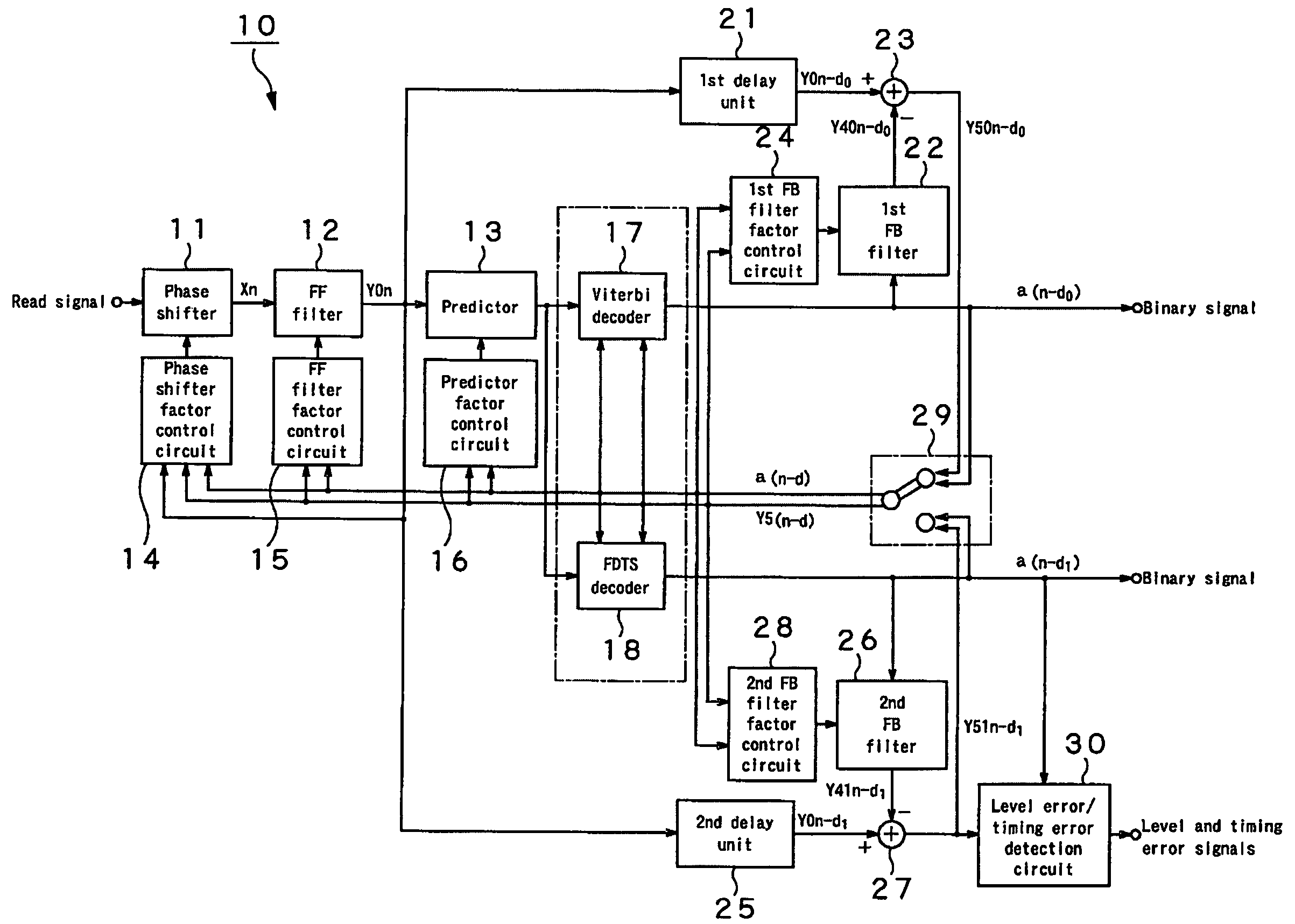
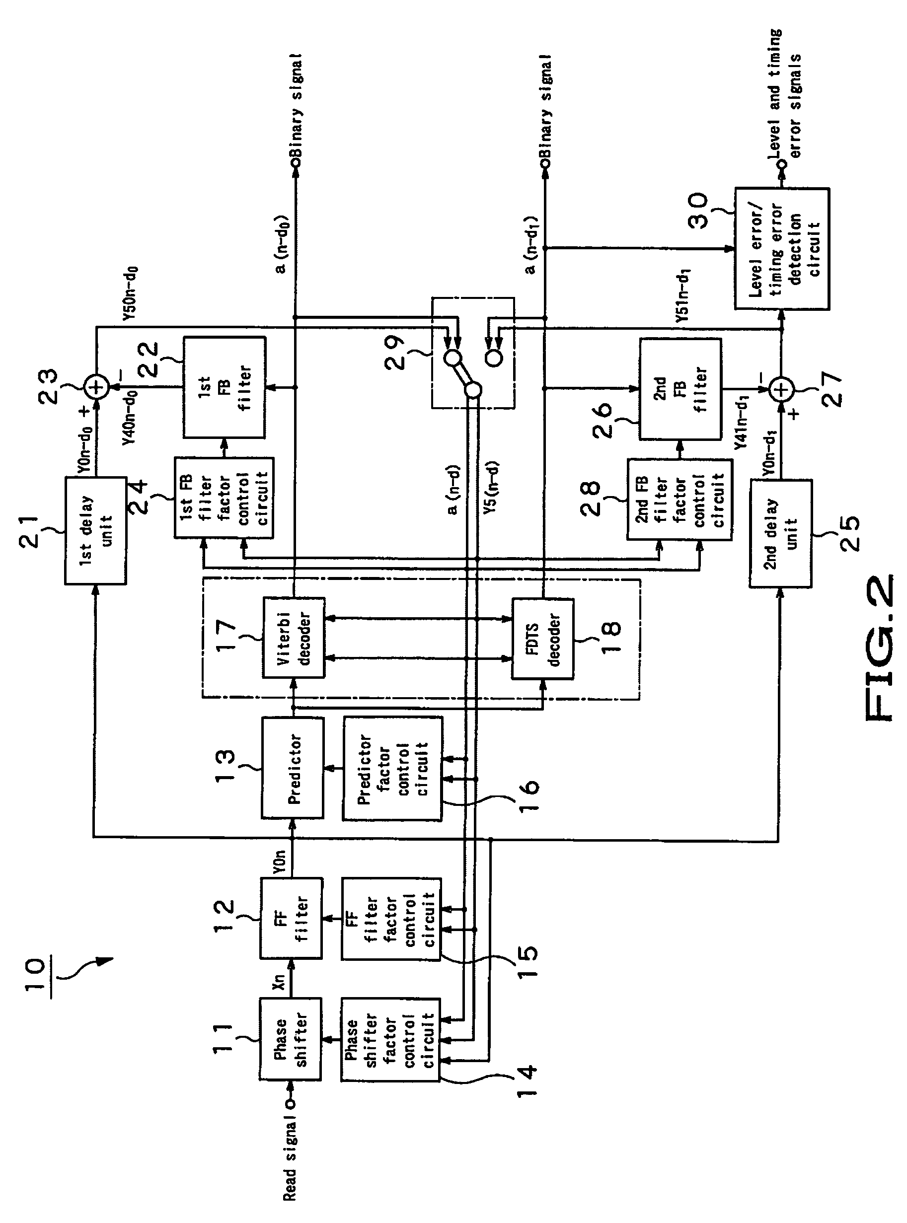
[0070]The present invention will be described in detail below concerning the adaptive equalizer as an embodiment thereof.

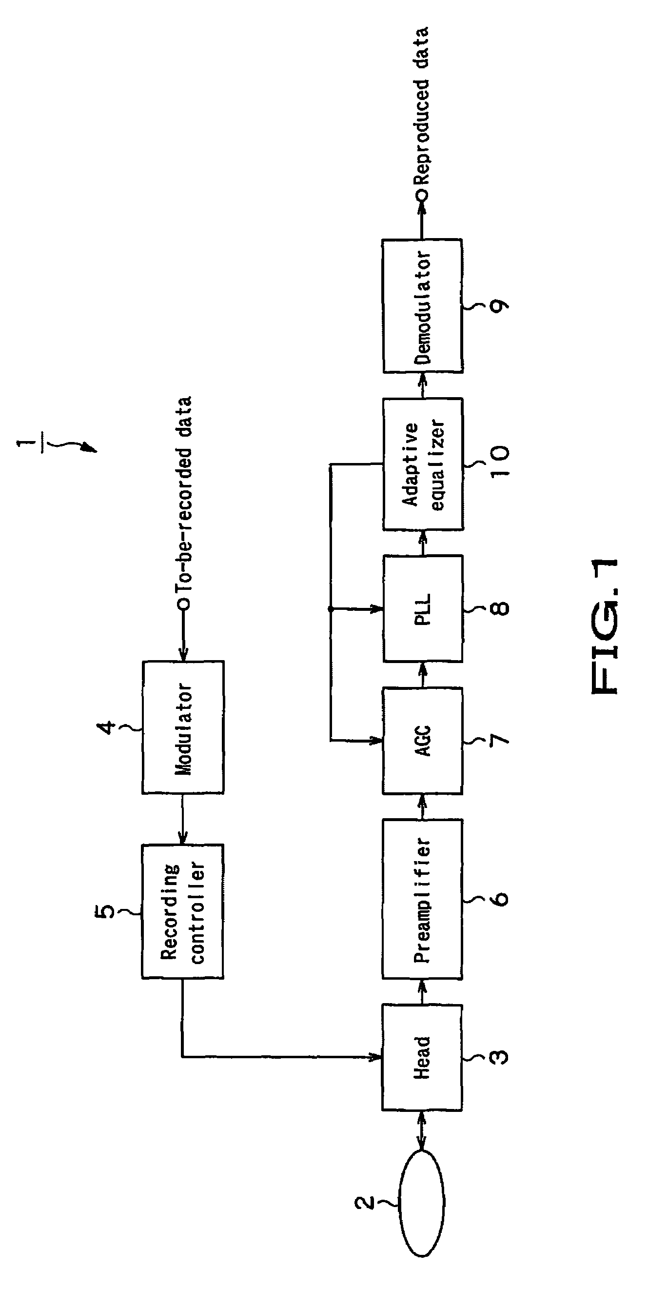
[0071]Referring now to FIG. 1, there is schematically illustrated in the form of a block diagram a recorder / player, generally indicated with a reference numeral 1, incorporating an adaptive equalizer 10 according to the present invention.

[0072]As shown in FIG. 1, the recorder / player 1 is an apparatus to write and / or read data to and / or from a disk-shaped recording medium 2 such as an optical disk, magnetic disk or the like. The disk-shaped recording medium 2 is capable of a signal recording which allows inter-symbol interference during playback on the presumption that the playback system is a transversal filter. Also, the disk-shaped recording medium 2 is a disk which records a row of coded data, and the data is read from the disk by the maximum-likelihood decoding such as Viterbi decoding or FDTS decoding.

[0073]The recorder / player 1 includes a head unit 3 which w...


PUM

PropertyMeasurementUnit
processing timeaaaaaaaaaa
processingaaaaaaaaaa
signal-to-noise ratioaaaaaaaaaa

Abstract

An adaptive equalizing apparatus that can positively remove the leading Inter Symbol Interference (ISI), make a maximum-likelihood decoding and an optimum equalization on the basis of the result of the maximum-likelihood decoding with consideration being given to the asymmetry of an input waveform. The adaptive equalizing apparatus includes a feedforward filter, a maximum-likelihood decoder, a feedback filter, a delay unit, and a subtracter. In the feedback filter, the tap factor is controlled on the basis of the binary signal generated by the maximum-likelihood decoding to generate a distortion of a partial response after the leading edge of the binary signal and an ISI response after the trailing edge. In the feedforward filter, the tap factor for the signal supplied from the subtracter is controlled to be a partial response.

Description

CROSS REFERENCES TO RELATED APPLICATIONS[0001]The present invention contains subject matter related to Japanese Patent Application JP 2004-115769 filed in the Japanese Patent Office on Apr. 9, 2004, the entire contents of which being incorporated herein by reference.BACKGROUND OF THE INVENTION[0002]1. Field of the Invention[0003]The present invention relates to an adaptive equalizing apparatus and method, used in an optical or magnetic recorder to make waveform equalization with a PRML (partial response maximum-likelihood) technique which is a combination of the partial response equalization and the maximum-likelihood decoding such as the Viterbi decoding, FDTS (fixed delay tree search) or the like.[0004]2. Description of the Related Art[0005]In a recorder using a superdense recording type optical disk such as the recently developed blue-ray disk (brand name), the playback system thereof is regarded as a transversal filter to make waveform equalization by the PRML technique which is...

Claims


Application Information

Patent Timeline
Patent Type & Authority Patents(United States)
IPC IPC(8): H03H7/30G11B20/10G11B20/18H03M13/00H03M13/41H04L25/03H04L27/00H04L27/06
CPCH04L25/03261H04L25/03267H04L25/03299H04L25/03171H04L25/03222H04L2027/003H04L2027/0053H04L2027/0085F21S9/03F21S8/00E01F9/615E01F13/00
Inventor HIGASHINO, SATORUKAJIWARA, YOSHIYUKI
Owner SONY CORP
Learn More