Semiconductor integrated circuit performing a voltage comparison and preventing deterioration of a voltage comparison accuracy
a technology of integrated circuits and capacitors, applied in the field of accurate comparator circuits, can solve the problems of deteriorating offset voltage correction accuracy and lower voltage held by the two capacitors, and achieve the effect of preventing deterioration of voltage comparison accuracy and improving voltage comparison accuracy
- Summary
- Abstract
- Description
- Claims
- Application Information
AI Technical Summary
Benefits of technology
Problems solved by technology
Method used
Image
Examples
first embodiment
[0033][Structure and Basic Operation]
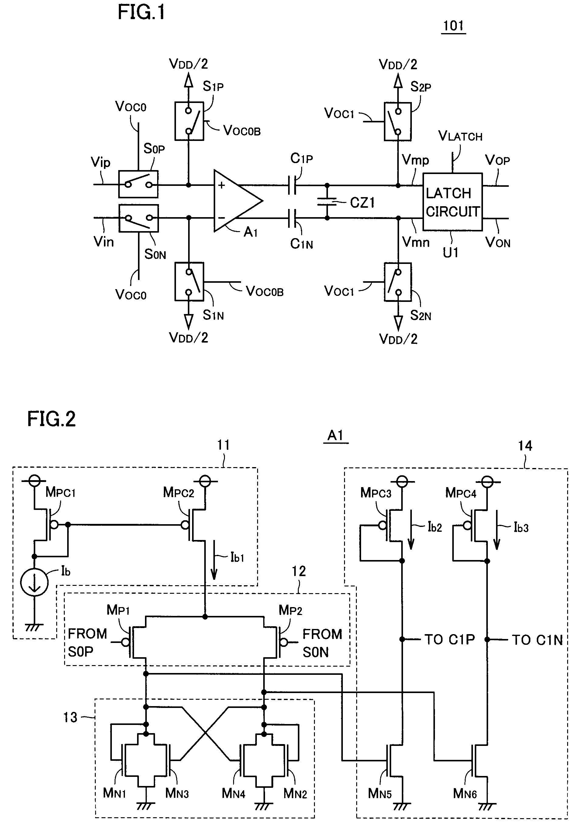
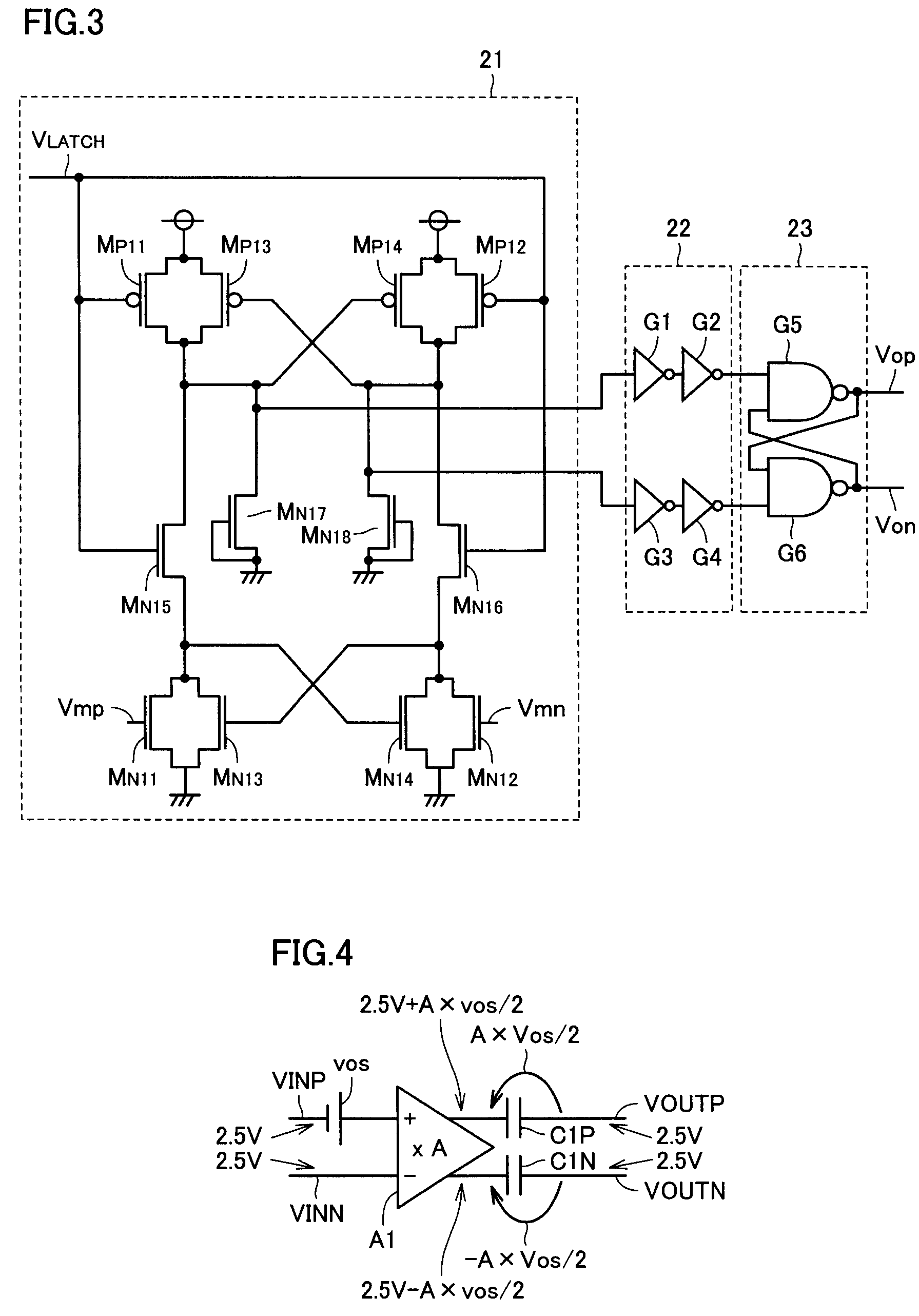
[0034]FIG. 1 shows a structure of a semiconductor integrated circuit according to a first embodiment of the invention.
[0035]Referring to FIG. 1, a semiconductor integrated circuit 101 is an OSS type comparator circuit, and includes an amplifier circuit (differential amplifier circuit) A1, capacitors (first, second and third capacitors) C1P, C1N and CZ1, switches S0P and S1P, a switch (first switch) S2P, switches S0N and S1N, a switch (second switch) S2N and a latch circuit U1. Each of switches S0P-S2P and S0N-S2N may be implemented by, e.g., a N-channel MOS transistor, a P-channel MOS transistor or a complementary switch formed of a combination of N- and P-channel MOS transistors.
[0036]Switch S0P has a first terminal receiving an input voltage Vip and a second terminal connected to a positive-phase input terminal (first input terminal) of amplifier circuit A1 and a first terminal of switch S1P.
[0037]Switch S0N has a first terminal receiving an in...
second embodiment
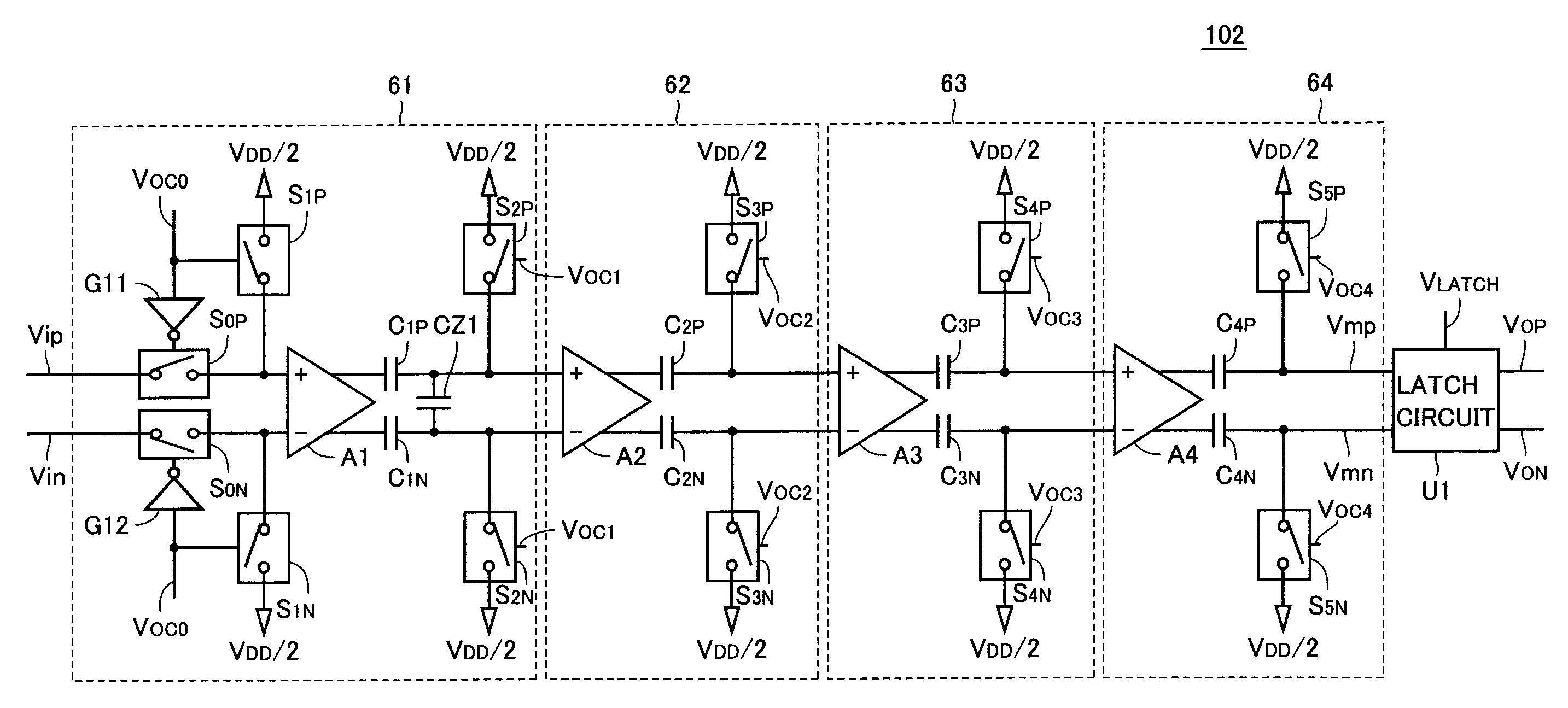
[0111]A second embodiment relates to a semiconductor integrated circuit that is different from that according to the first embodiment in that amplifier circuits are arranged in a plurality of stages. The semiconductor integrated circuit according to the second embodiment is substantially the same as that according to the first embodiment except for details described below.
[0112]FIG. 14 shows a structure of the semiconductor integrated circuit according to the second embodiment of the invention.
[0113]Referring to FIG. 14, a semiconductor integrated circuit 102 is an OSS type of comparator circuit, and includes amplifying units 61-64 and latch circuit U1. Amplifying unit 61 includes amplifier circuit (first differential amplifier circuit) A1, inverter circuits G11 and G12, capacitors (first, second and third capacitors) C1P, C1N and CZ1, switches S0P and S1P, switch (first switches) S2P, switches S0N and S1N, and switch (second switch) S2N. Amplifying unit 62 includes an amplifier cir...
third embodiment
[0147]This embodiment relates to a semiconductor integrated circuit in which each amplifying unit corresponding to that in the semiconductor integrated circuit according to the second embodiment employs a capacitor as a measure concerning the pulse current. The semiconductor integrated circuit according to the third embodiment is substantially the same as that according to the second embodiment except for the details described below.
[0148]FIG. 16 shows a structure of a semiconductor integrated circuit according to a third embodiment of the invention.
[0149]Referring to FIG. 16, a semiconductor integrated circuit 103 is an OOS type comparator circuit, and includes amplifying units 71-74 and latch circuit U1. Amplifying unit 71 has substantially the same structure as amplifying unit 61. Amplifying units 72-74 differs from amplifying units 62-64 in the semiconductor integrated circuit according to the second embodiment of the invention in that amplifying units 72-74 further include capa...
PUM
 Abstract
Description
Claims
Application Information
 - R&D
- Intellectual Property
- Life Sciences
- Materials
- Tech Scout
- Unparalleled Data Quality
- Higher Quality Content
- 60% Fewer Hallucinations
Browse by: Latest US Patents, China's latest patents, Technical Efficacy Thesaurus, Application Domain, Technology Topic, Popular Technical Reports.
© 2025 PatSnap. All rights reserved.Legal|Privacy policy|Modern Slavery Act Transparency Statement|Sitemap|About US| Contact US: help@patsnap.com


